Open topic with navigation
SSI Fundamentals
Synchronous Serial Interface (SSI) is a widely accepted controller interface. Position data from the sensor is encoded in a binary or Gray Code format and transmitted over a high-speed serial interface. Many types of transducers are available with SSI, including magnetostrictive displacement transducers (MDTs), absolute encoders, and laser measuring devices.
SSI has a number of advantages over other transducer interfaces:
-
High noise immunity
-
Absolute position
-
Supports a wide variety of transducers.
-
Many SSI devices offer higher precision; for example, magnetostrictive transducers with SSI output are commonly available with resolutions to 1 µm, and some offer 0.1 µm.
Important!
The RMC SSI inputs require RS-422 (5V differential) SSI inputs. They do
not support single-ended SSI inputs or higher voltage inputs.
SSI feedback is supported by the following modules:
The RMCs provide the following SSI options:
|
SSI Options
|
RMC75
MA Module
|
RMC150
SSI Module
|
RMC150
UI/O Module
|
RMC200 S8 Module
|
RMC200 U14 Module
|
|
Data Bits
|
8 to 32
|
8 to 31
|
8 to 32
|
8 to 32
|
8 to 32
|
|
SSI Format
|
Binary or Gray Code
|
Binary or Gray Code
|
Binary or Gray Code
|
Binary or Gray Code
|
Binary or Gray Code
|
|
SSI Errors
|
None, all zeros, all ones, or bit 21
|
None, all zeros, all ones, or bit 21
|
None, all zeros, all ones, or bit 21
|
None, all zeros, all ones, or bit 21
|
None, all zeros, all ones, or bit 21
|
|
Clock Rates
|
150, 250, 375 kHz
|
230, 921kHz
|
250, 500, 971kHz
|
100, 150, 250, 400, 625, 1000, 1500, 2500 kHz
|
100, 150, 250, 400, 625, 1000, 1500, 2500 kHz
|
|
Wire Delay
|
n/a
|
n/a
|
available
|
not yet available
|
not yet available
|
SSI Modes on the RMC
A standard SSI interface on an RMC consists of a Clock Output and Data Input. The RMC sends a clock signal to the SSI device, and the SSI device returns a data signal while the RMC is clocking.
Some RMC modules support additional SSI modes.
These modes are:
-
SSI Monitor
In SSI Monitor mode, the RMC SSI interface consists of a Clock Input and a Data Input. This allows the RMC to listen to the SSI traffic between a separate controller and a device.
-
SSI Device
In SSI Device mode, the RMC SSI interface consists of a Clock Input and a Data Output. This allows the RMC to act like an SSI device. That is, when another controller sends a clock signal to the RMC, the RMC will send the data.
-
SSI Output
In SSI Output mode, the RMC SSI interface consists of a Clock Output and a Data Output. This allows the RMC to send data to an SSI Monitor. This can be used to send data from an RMC150 UI/O module to another controller's SSI Monitor input.
These modes are supported by configuring the modules listed below as follows:
|
Mode
|
RMC75
MA Module
|
RMC150
SSI Module
|
RMC150
UI/O Module
|
RMC200
S8 Module
|
RMC200
U14 Module
|
|
SSI Input
|

|
|
|
|
|
|
SSI Monitor
|
|
|
|
|
|
|
SSI Device
|
|
|
|
|
*
|
|
SSI Output
|
|
|
|
|
|
*Via the SSI Echo mode, which echoes the channel 0 data onto channel 1, with channel 1 as an SSI device.
Configuring the SSI Modes
Follow the steps below to set up each SSI mode:
RMC150 UI/O Module
Follow the instructions in Configuring UI/O High-Speed Channels to set up a channel, with the follow settings for the desired SSI mode:
-
SSI Monitor: Choose SSI Axis Input or SSI Register Input. Then, in Axis Parameters, on the All tab, expand Feedback, and set the SSI Clock Mode to Monitor.
-
SSI Device: Choose SSI Output and set the SSI Output Mode to Slave.
-
SSI Output: Choose SSI Output and set the SSI Output Mode to Master.
RMC200 S8 Module
The only mode other than the standard SSI mode is the SSI Monitor mode that uses inputs 6 and 7.
-
In the Project Pane, expand the Modules folder.
-
Double-click the desired S8 module and choose Configuration.
-
Select One SSI Monitor Input.
-
Click OK.
RMC200 U14 Module
Follow the instructions in Configuring U14 High-Speed Channels to set up a channel, with the follow settings for the desired SSI mode:
-
SSI Monitor: Choose SSI Monitor input.
-
SSI Echo: Set Channel 0 to SSI/MDT input, and set Channel 1 to SSI Echo output.
For more details on configuring, see the Configuring UI/O High-Speed Channels, Configuring U14 High-Speed Channels, and Configuring S8 Channels.
Synchronized SSI for Linear Magnetostrictive Transducers
When using magnetostrictive SSI transducers, it is highly recommended that a synchronized SSI transducer be selected. This ensures that the time between position samples matches the control loop time of the RMC controller. If the transducer is not synchronized, the sample time may not match and will adversely affect control. When the sample time does not match the loop time it introduces jitter to the position measurement which gets worse as the axis speed increases. Make sure to specify that the transducer be of the synchronized type.
Synchronized SSI is not an issue for rotary encoders.
SSI Advantages
SSI transducers and absolute encoders offer the following advantages:
-
High resolution. Down to 0.1 μm (approx. 0.000004") for linear SSI transducers.
-
Noise immunity
-
Cost effective data transfer (only one 5-wire cable with shield is needed)
-
Transmission rate independent of data length and resolution
-
Transmission over long distances
-
Direct connection to the RMCs SSI axis module
Data Format
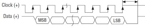
To read an SSI position, the RMC sends clock pulses to the transducer and the SSI device returns the data as follows:
-
The SSI channel sends the first clock pulse by setting the Clock signal low, then high.
-
On the first rising edge of the Clock signal, the SSI transducer returns the most-significant bit of the data on the Data line.
-
The SSI channel sends the second clock pulse by setting the Clock signal low, then high. When the Clock signal goes high, the SSI channel samples the bit on the Data line. When the SSI device sees the clock signal go high, it places the second bit of data on the Data line.
-
This continues until all bits have been clocked and sampled.
-
The value obtained from the SSI data is put in the Raw Counts register for that axis. The Raw Counts are converted to Counts and then into an Actual Position in user-defined units.
SSI Cable Length
The maximum allowable SSI cable length depends on the SSI Clock Rate. For SSI inputs on the UI/O module, wire delay compensation is available to allow longer lengths, as described in the Wire Delay Compensation section below.
|
Clock Rate
|
Maximum Cable Length*
|
|
100 kHz
|
2100 ft (640 m)
|
|
150 kHz
|
1360 ft (415 m)
|
|
230 kHz
|
850 ft (255 m)
|
|
250 kHz
|
770 ft (235 m)
|
|
375 kHz
|
475 ft (145 m)
|
|
400 kHz
|
450 ft (135 m)
|
|
500 kHz
|
325 ft (99 m)
|
|
625 kHz
|
225 ft (70 m)
|
|
921 kHz
|
120 ft (37 m)
|
|
971 kHz
|
110 ft (34 m)
|
|
1000 kHz
|
100 ft (30 m)
|
|
1500 kHz
|
25 ft (7.5 m)
|
|
2500 kHz
|
3 ft (1 m)
|
* The cable lengths are approximate, and may be affected by the type of wire and transducer.
Wire Delay Compensation (RMC150 UI/O Module Only)
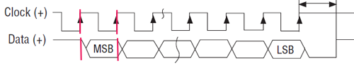
Wire delay compensation is available on the RMC150 Universal I/O Module and is required for SSI wire runs that exceed the lengths given in the SSI Cable Length section above. If the wire to the SSI device is very long, there will be a significant delay between the clock signal and the returned data signal. As shown in the diagrams below, if this delay exceeds one clock period, the RMC will not receive the correct data, unless the SSI Wire Delay parameter is used.
Minimal Delay
The timing diagram below shows an SSI system with very little delay. On the first rising edge of the Clock, the SSI device puts the first bit of data on the Data line. By the next rising edge of the Clock, when the RMC samples the data, the data is valid, and the read is successful.
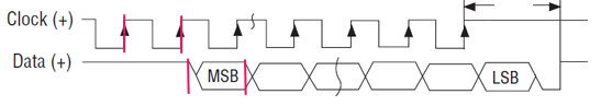
Excessive Delay
The timing diagram below shows an SSI system with a time delay of more then one clock period. On the first rising edge of the Clock, the SSI device puts the first bit of data on the Data line. By the next rising edge of the Clock, when the RMC samples the data, the data from the SSI device has not yet arrived, and the SSI input will not return the correct value.
To compensate for the delay, set SSI Wire Delay parameter. You can enter the wire length or enter the time delay directly. The SSI input will then use the delay value to correctly read the SSI input data.
Transducer Lengths
Magnetostrictive linear transducers with SSI output may require a minimum time between interrogation based on the length of the transducer. Check your transducer data sheet for details. Increasing the Loop Time of the RMC will increase the maximum allowed length of the transducer. See the MDT Fundamentals topic for details.
Setting up Axes with SSI Feedback
To set up axes with SSI feedback, read the following topics:
Note:
The RMC150 UI/O
and RMC200 U14
high-speed channels must be configured as SSI before being used as SSI
inputs.
The following parameters must be also set for axes with SSI feedback:
See Also
Feedback Resolution | Wiring Guidelines
Send comments on this topic.
Copyright © 2026 Delta Computer Systems, Inc. dba Delta Motion