Magnetostrictive Displacement Transducers (MDT) are absolute position transducers designed for use in rugged industrial environments. Early MDT sensors employed the Start/Stop or Pulse Width Modulated (PWM) signals. Delta generally refers to these signal types as MDT signals. Magnetostrictive Displacement Transducers can also have other types of outputs, such as analog or SSI.
MDTs are non-contact, wear-free, highly reliable, and offer accurate and repeatable linear position measurement. In the motion control industry, magnetostrictive displacement transducers are typically inserted into hydraulic cylinders for measurement of the cylinders position.
MDT feedback (Start/Stop or PWM) is supported by the following modules:
RMC75:MA axis module
Each axis on the RMC75 MA axis module can be individually configured for MDT or SSI inputs.
RMC150:MDT module
RMC200: S8 Module, U14 Module
Each MDT axis can be configured for a Start/Stop transducer or a Pulse Width Modulated (PWM) transducer.
Start/Stop
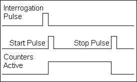
To make a measurement with a Start/Stop transducer, the RMC sends an interrogation pulse to the transducer. The transducer responds by returning 2 pulses—a Start pulse and a Stop pulse. The RMCs internal counters begin to count when the first pulse, Start, is received and stop counting when the second pulse, Stop, is received. The time between the start pulse and the stop pulse is proportional to the transducer position.
Start/Stop Pulse Transducer
Blanking Period (For Neuter Outputs)
After the RMC receives the start pulse, it waits a brief amount of time before looking for the stop pulse. This time, called the MDT blanking period, gives time for noise to settle out.
The RMC150 and RMC200 have an MDT Blanking Period parameter, with options of 5µsec or 21µsec. The default value is 5µsec. Some older transducers, such as Temposonics I and II with neuter outputs, require the longer blanking period of 21µsec, due to noisy signals.
The RMC75 does not have an MDT Blanking Period parameter and always uses a 5µsec blanking period. Therefore, Temposonics I and II transducers with neuter outputs should not be used with the RMC75, but can be used with the RMC150 or RMC200.
PWM
To make a measurement with a Pulse Width Modulated transducer, the RMC sends an interrogation pulse to the transducer. The transducer responds with a return signal. The return signal is high while the transducer is determining its position. The RMC counts during the time that the return signal is high. The time that the return signal is high is proportional to the transducer position.
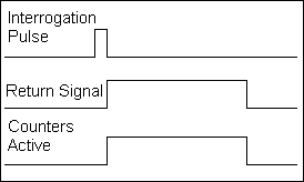
Pulse Width Modulated Transducer
The value obtained from the PWM or Start/Stop counter is put in the Raw Counts register for that axis. The Raw Counts are converted to Counts and then into an Actual Position in user-defined units.
Resolution
The resolution of MDT sensors depends on the RMC's clock speed for timing the pulses. For MDT Start/Stop or PWM feedback with a typical calibration value of approx. 9 µs/in, the maximum resolution supported by the RMCs is as follows:
|
Module |
Maximum Resolution with one recirculation |
|
RMC75 MA |
0.0005 |
|
RMC150 MDT |
0.001 |
|
RMC200 S8 |
0.0005 |
|
RMC200 U14 |
0.0005 |
Delta does not recommend using recirculations on MDT transducers. Recirculations have historically been used to gain more accuracy in the measurement. However, with faster counters on the controller, recirculations have become less important. In addition, the highest accuracies are only available for MDT transducers with SSI output, which don't have any recirculation options.
An MDT transducer takes a certain amount of time to determine its position. The time it takes increases with position. Therefore, the length of the transducer dictates the minimum Loop Time you can use.
The approximate formula for determining the maximum transducer length for a given loop time is as follows:
Length(in.) = (LoopTime(ms) - 0.22)/0.0095
Using the formula, the following are approximate maximum lengths for a given loop time. The actual maximum length will vary slightly by RMC model. This assumes no recirculations.
|
Loop Time |
Maximum MDT Transducer Length |
|
125µs1 |
5 inches2 |
|
250µs |
11 inches2 |
|
500µs |
29.4 inches |
|
1000µs |
82.1 inches |
|
2000µs |
187.3 inches |
|
4000µs |
397.9 inches |
1 125µs Loop Time only available on RMC75 and RMC200 series.
2 Estimated max transducer length
Start/Stop and PWM Cable Length
For magnetostrictive sensors with Start/Stop or PWM signals, there is no set maximum cable length. Modern sensors use RS-422 for these signals, and can typically work with cables lengths of up to 4000 ft, using proper twisted-pair, shielded cable. Older, single-ended signals cannot transmit as far.
See Also
Feedback Resolution | Wiring Guidelines
Copyright © 2026 Delta Computer Systems, Inc. dba Delta Motion