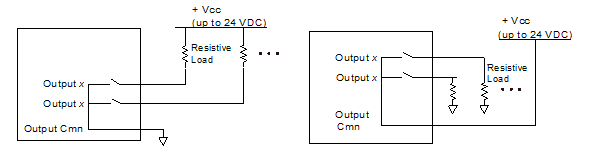
Figure 1: SSR switching resistive load: low-side configuration.
Figure 2: SSR switching resistive load: high-side configuration.
This topic covers the wiring of the discrete inputs and outputs on the RMC150 UI/O module (UI/O or U). See Wiring Guidelines for general wiring information.
Wire clamp screws must be tightened to max 2.2 lb-in (0.25 Nm).
UI/O Analog Inputs
Wire the analog inputs according to the RMC150 Analog Wiring topic.
UI/O Discrete Outputs
The UI/O points configured as outputs are solid state relays. When they are ”off” they have high impedance, and when ”on” they have low impedance (50Ω maximum, 25Ω typical). The user must power the outputs externally. The maximum current and voltage for the outputs is 75 mA (50 mA for Class I, Div 2) and 30 V.
Outputs can be wired in either a high-side or low-side configuration. Because all the outputs share the Output Common, all outputs on the same module must be wired the same.
Using Outputs with Resistive Loads
|
|
|
|
Figure 1: SSR switching resistive load: low-side configuration. |
Figure 2: SSR switching resistive load: high-side configuration. |
The load resistance must be sized such that the maximum current through the SSR does not exceed 50mA. The maximum current is calculated with the following equation:
Current = Vcc / RLoad
For example, if the supply voltage Vcc is 24V, and the load resistance is 480Ω, the current will be:
Current = 24Ω / 480Ω = 50mA
which is right at the 50mA limit. The load resistance should not be decreased any further with a 24V supply voltage.
Using Outputs with Inductive Loads
External fuses should be used to protect the SSRs if there is a possibility of over-current. When switching inductive loads, it is important to place a diode or tranzorb across the load to protect the switch when transitioning from an ”ON” to an ”OFF” state. Otherwise, the collapsing magnetic field can cause a reverse voltage spike in excess of the 30 V rating of the SSR. See figures below for details.
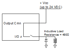
Figure 3: SSR switching inductive inductive load: high-side configuration.
![]() Example: Calculating maximum current
for inductive load.
Example: Calculating maximum current
for inductive load.
UI/O Discrete Inputs
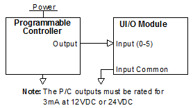
The UI/O points configured as inputs use the Input Common and are compatible with signal levels ranging from 12V to 24V. Each input draws a maximum of 2.6mA with a 12V or 24V input. Most PLC outputs can be connected to the UI/O inputs directly.
Because the I/O points share a single common, the inputs must all be connected to the same type of output (sinking or sourcing). If your application has various types of outputs, see figure 9 to convert a sinking output to a sourcing output.
Wiring Diagrams
The following are some input wiring diagrams:
|
|
|
Figure 4: Direct connection to the input. |
|
|
|
|
Figure 5: Direct connection to Programmable Controller. |
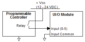
Figure 6: Relay Connection from Programmable Controller. |
Using UI/O Inputs with Open Collector Outputs
The UI/O's discrete inputs can be used with open collector (sinking) outputs. There are three configurations that can be used to drive the UI/O inputs from an open-collector output:
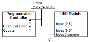
Figure 7: PNP Configuration: This configuration is the most popular for open collector PNP outputs.
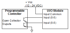
Figure 8: Open Collector Outputs to UI/O Inputs with Input Common Connected to Vcc.
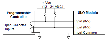
Figure 9: Open Collector Outputs to UI/O inputs with input common connected to ground. Typically not recommended due to the required external resistors and a continuous current draw, and the fact that the logic becomes inverted. May be necessary for mixing sourcing and sinking outputs.
For 24VDC power, the pull-up resistor should be a 4.7kΩ, ¼ watt resister. The output must be capable of switching 2.6mA when closed. When the open collector output is open, the DI/O input sees 11.8V @ 2.6mA.
For 12VDC power, the pull-up resistor should be a 1 kΩ, ¼ watt resister. The output must be capable of switching 2.6mA when closed. When the open collector output is open, the DI/O input sees 9.4V @ 2.6mA.
UI/O Quadrature Channel
Channels configured as Quadrature inputs should be wired as follows.
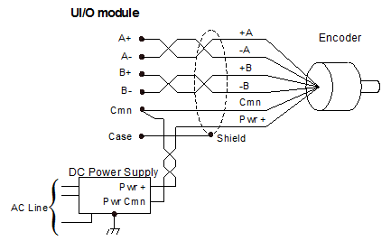
The A and B inputs interfaces only to 5V differential line driver (RS-422) signals. Higher voltages will require a signal converter, available from 3rd party suppliers. Single-ended (TTL) transducers are not supported due to low noise immunity. Always use twisted-pairs for the A and B signals. Do NOT connect the transducer Ground or Cmn to the cable shield, Case, or earth ground. The user must supply power for the transducer or encoder.
Termination
Termination is software selectable and should always be used. If quadrature inputs are daisy-chained, apply termination only to the last input.
After setting up the UI/O input as quadrature, and assigning the input to an axis, the Input Termination parameter will be available on the All tab in the Axis Parameters Pane, in the Feedback section. Choose ±A and ± B to apply termination.
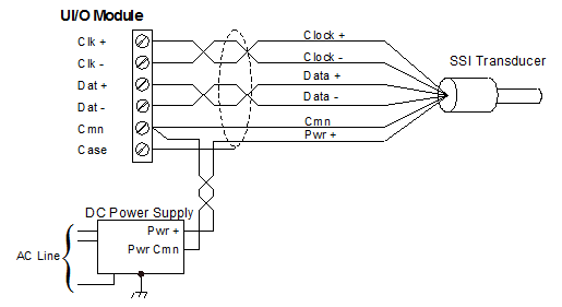
UI/O SSI Channels
The SSI Clock and Data pins interface only to 5V differential line driver (RS-422) signals. Always use twisted-pairs for the Clock and Data signals. Do NOT connect the transducer Ground or Cmn to the cable shield, Case, or earth ground. The user must supply power for transducers or encoders.
Maximum SSI Cable Length
For SSI inputs on the UI/O module, wire delay compensation is available. If your cable length exceeds the length for your clock rate given in the table below, you should use the SSI Wire Delay parameter to account for the time delay of the SSI signal:
|
Maximum Cable Length* |
|
|
250 kHz |
770 ft (235 m) |
|
500 kHz |
325 ft (99 m) |
|
971 kHz |
110 ft (34 m) |
* The cable lengths are approximate, and may be affected by the type of wire and transducer.
SSI Inputs
Channels configured as SSI inputs and interfacing to transducers or encoders should be wired as follows.
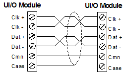
SSI, UI/O to UI/O
SSI channels configured for communicating between RMCs should be wired as follows.
SSI Monitor Mode
SSI Register Input mode can be used with Monitor Mode to monitor the communication between another RMC and an SSI transducer or encoder, thereby synchronizing multiple RMCs to one SSI device.
When wiring a daisy-chained SSI system, the SSI master (the UI/O) should be on one end of the daisy chain with the SSI device on the other end, and any monitoring UI/O modules in the middle of the daisy chain.
Wire the SSI device to the first monitoring RMC as illustrated in the SSI Inputs section above, then daisy chain the first RMC to the other RMCs as illustrated in the SSI,UI/O to UI/O section above. Apply termination only to the SSI master.
Termination
Termination is software selectable and should always be used. If SSI inputs are daisy-chained, apply termination only to the last input.
For channels configured as SSI Axis Input, after assigning the input to an axis, the Input Termination parameter will be available on the All tab in the Axis Parameters Pane, in the Feedback section. Choose ±Data to apply termination.
For all other SSI channel configurations, the SSI Termination option is provided in the UI/O Properties dialog when configuring the Quad/SSI channels.
See Also
Copyright © 2026 Delta Computer Systems, Inc. dba Delta Motion