SSI Wire Delay
Description
This parameter is valid on axes with SSI feedback
on the UI/O
Module. The SSI Wire Delay allows the SSI input to take into account
the delay of the signal in the wire. To ensure error-free feedback, this
parameter should be used if the wire length exceeds the values given in
the table below.
|
Clock Rate
|
Maximum Cable Length*
|
|
250 kHz
|
770 ft (235 m)
|
|
500 kHz
|
325 ft (99 m)
|
|
971 kHz
|
110 ft (34 m)
|
*Note:
The cable lengths depend on the type of wire used and on the internal delays
in the transducers. The transducer delays are usually not specified so
the wire delay may need to be found empirically.
Setting the Wire Delay
To set the SSI Wire Delay parameter:
-
In the Axis Parameters, select the SSI Wire Delay parameter and then click the ellipsis button  .
.
-
Enter the Delay Time directly, or choose to estimate the delay based on the cable length. The Wizard will calculate and/or adjust the Wire Delay Time to account for resolution of the internal delay timer. The wizard will display the value that will be applied.
-
Click OK. The time to delay will be converted to the nearest time delay that can be represented with [1..8] * [0..31] / 33MHz.
Details
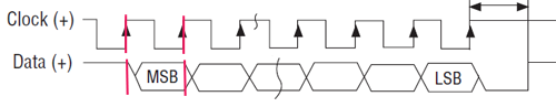
Minimal Delay
The timing diagram below shows an SSI system
with very little delay. On the first rising edge of the Clock, the SSI
device puts the first bit of data on the Data line. By the next rising
edge of the Clock, when the RMC samples the data, the data is valid, and
the read is successful.
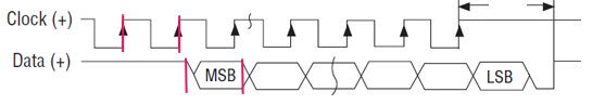
Excessive Delay
The timing diagram
below shows an SSI system with a time delay of more then one clock period.
On the first rising edge of the Clock, the SSI device puts the first bit
of data on the Data line. By the next rising edge of the Clock, when the
RMC samples the data, the data from the SSI device has not yet arrived,
and the SSI input will not return the correct value.
To compensate for
the delay, set SSI Wire Delay parameter.
You can enter the wire length or enter the time delay directly. The SSI
input will then use the delay value to correctly read the SSI input data.
See Also
Parameter Registers
| SSI/MDT Configuration Register
| SSI
Fundamentals
Send comments on this topic.
Copyright © 2025 Delta Computer Systems, Inc. dba Delta Motion