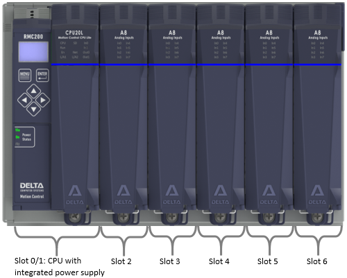
RMC200 Lite:
Slot 0/1: CPU module with integrated power supply
Remaining slots: I/O modules
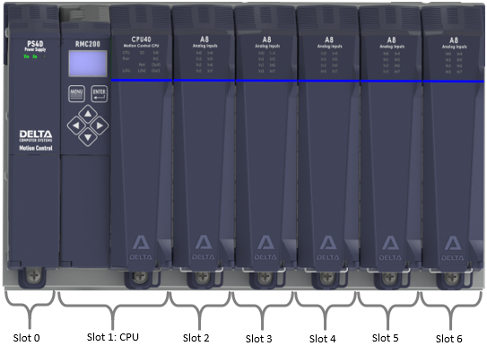
RMC200 Standard:
Slot 0: Power supply module
Slot 1: CPU module
Remaining slots: I/O modules
The RMC200 offers many controller features for controlling a wide variety of hydraulic, electric, and pneumatic position and position–pressure or position-force applications. The built-in 10/100 Ethernet ports provide connectivity to many PLCs and HMIs.
The RMC200 offers Lite and Standard options.
|
CPU |
Bases |
Max Control Axes (Physical and EtherCAT) |
Max Control Loops |
Max Total Axes, including Virtual, Reference, and Outer Loop |
|
|
Lite |
CPU20L, with integrated power supply |
18 |
36 |
48 |
|
|
Standard |
50 |
100 |
128 |
See Comparing RMC200 Lite and Standard for more details.
Feature Key
The Feature Key specifies the control features of the RMC200. Currently, it specifies the number of control loops.
The key is a removable token installed in the CPU module. This allows for easy transfer from one RMC200 CPU to another when replacing one RMC200 with a spare RMC200. When initially purchased, the Feature Key comes loaded with the customer-ordered features. Features may also be added to the Feature Key later.
Modules
The RMC200 consists of a backplane with user-swappable power, CPU, and I/O modules.
|
RMC200 Lite: Slot 0/1: CPU module with integrated power supply Remaining slots: I/O modules
|
|
|
RMC200 Standard: Slot 0: Power supply module Slot 1: CPU module Remaining slots: I/O modules |
|
|
Module |
Description |
|
Backplanes |
|
|
5-slot Lite base |
|
|
7-slot Lite base |
|
|
5-slot Standard base |
|
|
7-slot Standard base |
|
|
11-slot Standard base |
|
|
15-slot Standard base |
|
|
Power Supplies |
|
|
35 W, 24 VDC input power supply, for the B5, B7 and B11 bases |
|
|
50 W, 24 VDC input power supply, for the B15 base |
|
|
CPUs |
|
|
Up to 18 physical control axes (number of control loops purchased separately, specified by the Feature Key) |
|
|
Up to 50 physical control axes (number of control loops purchased separately, specified by the Feature Key) |
|
|
Communication Modules |
|
|
2 EtherCAT ports, provides EtherCAT MainDevice functionality |
|
|
I/O Modules |
|
|
4 Control Outputs (±10 V, 4-20 mA, ±20 mA) |
|
|
8 Control Outputs (±10 V only) |
|
|
8 SSI, Start/Stop, or PWM Inputs, supports one quadrature input or one SSI monitor input |
|
|
8 Analog Inputs (±10 V, 4-20 mA) |
|
|
8 Load Cell Inputs, ±5 mV/V, with Sense Input |
|
|
4 Quadrature Encoder Inputs, supporting RS-422, HTL, or TTL, with home and registration inputs |
|
|
4 Analog Inputs, 2 Analog Outputs, 4 Discrete I/O, and 2 High-Speed channels for SSI, MDT, or quadrature encoder inputs, each with an extra high-speed discrete input |
|
|
20 configurable I/O, 4 fixed high-speed inputs for general purpose inputs, or 2 quadrature encoder inputs, or 2 pulse counter inputs |
|
Installing and Removing Modules
To install a module on the backplane:
|
1. Tilt the module backwards. |
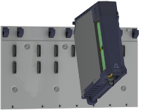
|
|
2. Insert the module's hinge pins into the backplane hooks. |
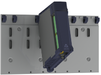
|
|
3. Tilt the module down. |
 |
|
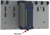
4. Tighten the screw to
|
Removal is the reverse of installation.
The maximum power dissipation of each RMC module is listed below.
|
Module |
Power |
|
2.0 W |
|
|
2.7 W |
|
|
2.5 W |
|
|
2.7 W |
|
|
3.0 W |
|
|
3.2 W |
|
|
7.0 W |
|
|
10 W |
|
|
9.0 W, includes power dissipation of integrated power supply |
|
|
8.0 W |
|
|
2.0 W |
|
|
1.4 W, all analog outputs in voltage mode 2.8 W, all analog outputs in current mode |
|
|
2.0 W |
|
|
1.8 W |
|
|
1.4 - 2.4 W, depending on use of Exciter Output |
|
|
1.4 - 2.4 W, depending on use of Exciter Output Note: Max power consumption is 1.3 W with no Exciter Output, 3.2 W with Exciter Output |
|
|
1.4 W |
|
|
2.6 W, both analog outputs in voltage mode 3.2 W, both analog outputs in current output |
|
|
1.0 W, plus 50 mW per I/O point used |
General Specifications
See also RMC200 Mounting.
|
Mechanical |
|
|
Mounting |
Panel-mount |
|
Dimensions B5L |
7.0x 7.9 x 5.8 in. (WxHxD) (177 x 200.0 x 146 mm), with mounting lugs |
|
Dimensions B7L |
9.7 x 7.9 x 5.8 in. (WxHxD) (246 x 200.0 x 146 mm), with mounting lugs |
|
Dimensions B5 |
7.9 x 7.9 x 5.8 in. (WxHxD) (200 x 200.0 x 146 mm), with mounting lugs |
|
Dimensions B7 |
10.7 x 7.9 x 5.8 in. (WxHxD) (270 x 200.0 x 146 mm), with mounting lugs |
|
Dimensions B11 |
16.2 x 7.9 x 5.8 in. (WxHxD) (410 x 200 x 146 mm), with mounting lugs |
|
Dimensions B15 |
21.9 x 7.9 x 5.8 in. (WxHxD) (555 x 200 x 146 mm), with mounting lugs |
|
Environment |
|
|
Operating temperature |
-4 to +140°F (-20 to +60°C) |
|
Storage temperature |
-40 to +185°F (-40 to +85°C) |
|
Humidity |
Non-condensing |
|
Agency compliance |
CE, UL, CUL |
See Also
RMC200 Part Numbering | RMC200 Mounting Instructions | Comparing RMC200 Lite and Standard
Copyright © 2026 Delta Computer Systems, Inc. dba Delta Motion