Custom feedback gives the flexibility to use feedback from a source other than directly from a hardware input. Custom feedback requires that the user create a user program that continuously calculates some value to be used by the axis for feedback. Custom feedback requires firmware 3.54.0 or newer. Notice that simulate mode is not available for axes with custom feedback.
Custom feedback has many uses, including the following applications:
Controlling to the sum, difference, or average of feedback devices
Custom feedback makes it possible to control to the sum of the forces of multiple hydraulic cylinders, control the difference between two actuators, or control the average of actuator positions.
Switching feedback
Switching feedback for an axis is useful in certain testing applications, or for using several transducers to provide the desired resolution over the range of the feedback.
For details, see Switching Feedback using Custom Feedback.
Feedback linearization
Feedback linearization refers to either "straightening" the output of a transducer to make up for its nonlinearity, or calculating the measurement of some point that is geometrically related to the transducer measurement, such as calculating the end of a swing arm based on the position of the cylinder that moves the swing arm.
Feedback linearization can de done using curves or a mathematical formula. For details, see Feedback Linearization using Curves and Feedback Linearization using Mathematical Formula.
Redundant feedback
If one of multiple feedback devices fails, the system can continue operating without interruption.
For details, see Redundant Feedback using Custom Feedback.
How It Works
Axes defined with custom feedback do not have an assigned physical feedback. Rather, they have an _Axis[].CustomCounts register (_Axis[].SecCustomCounts for secondary inputs) that can be written to. You must create a user program that continuously calculates the feedback value and assigns it to this register.
The _Axis[].CustomCounts or _Axis[].SecCustomCounts value will have the Scale and Offset applied to it, and the result then appears in the Actual feedback register for that axis, whether it be Actual Position, Actual Velocity, Actual Pressure, Actual Force or Actual Acceleration. Typically, the Scale and Offset are left at their default values of 1 and 0, which means that the Custom Counts value remains unchanged and the value you want as the feedback can be directly written to the _Axis[].CustomCounts or _Axis[].SecCustomCounts register.
Limitations
Custom feedback has the following implications:
The RMC must always be in RUN mode
One task will be continuously running the user program that is performing the custom feedback calculations. You must make sure this program always runs, as described below.
Auto-tuning cannot be used, since auto-tuning requires that the RMC be in PROGRAM mode. Auto-tuning may be used for other axes in the RMC, but the custom feedback axes can not be operating while auto-tuning other axes.
Rotary axes are not supported by custom feedback.
Setting Up and Using Custom Feedback
Planning Number of Axes
Applications making use of custom feedback usually require the use of extra reference axes. This may result in exceeding the total number of axes available, particularly in the RMC75, which is limited to four axes.
For example, consider a single-axis position feedback linearization application utilizing custom feedback. Without custom feedback, a single-axis position application uses one axis in the RMC. However, the custom feedback will require two axes: the control axis, which will use custom feedback, and a reference axis, which will use the physical input from the position transducer.
Make sure to carefully determine the axis usage so that it does not exceed the number of axes available, which is listed in Axis Types Overview. A reference axis is counted as one axis.
Define the Axes
Custom feedback is supported by all axis types with feedback, except differential force or differential acceleration.
To define an axis with custom feedback:
Begin defining an axis as usual in the Axis Definitions dialog.
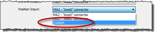
For the feedback of the axis, choose the type you need, such as position, velocity, pressure, etc.
Instead of choosing a physical input, choose Custom.
You will also need to create reference axes for each physical input that will be used together with the Custom Feedback axis.
Make a User Program to Continuously Assigns a Value to Custom Feedback
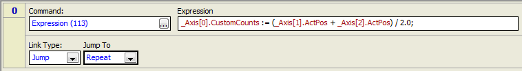
Create a user program that continuously writes to the _Axis[].CustomCounts or _Axis[].SecCustomCounts register. The user program should consist of one step that jumps back to itself. The step should have an Expression (113) command to do the calculation.
For example, this user program calculates the average of two positions and assigns it to the Axis 0 Custom Counts register. Notice that this program does not yet properly handle errors, as described in the Error Handling section below.
Make Sure the User Program Always Runs
This involves several steps:
Set the RMC to start in RUN mode.
In the Project Pane, right-click Programming and choose Properties.
On the RUN/PROGRAM page, set the Startup Mode to RUN.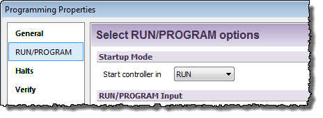
Click OK.
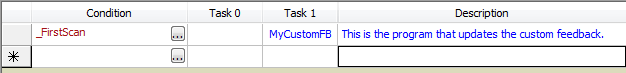
Start the user program when the RMC enters RUN mode.
In the Program Triggers, create a _FirstScan condition.
In one of the task columns, choose the user program you created. Make sure no other user programs will ever run on that task.
Make sure the Task does not stop when an axis halts.
In the Project Pane, right-click Programming and choose Properties.
On the Halts page, choose Stop the Following Tasks.
Uncheck the box for the task that will be running the user program.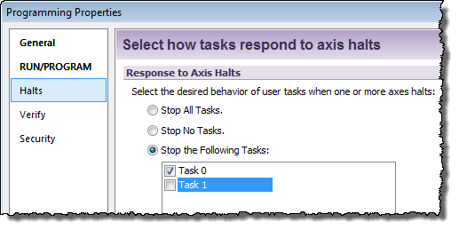
Verify the Custom Feedback is Correct
Before verifying that the custom feedback value updates correctly, you will need to make sure the other feedback values used in the calculation are correct. For example, it your custom feedback calculates the average of two physical pressure inputs, make sure those pressure inputs are set up properly and operating correctly before verifying the custom feedback.
To verify the custom feedback:
Make sure the axis is in RUN mode, and the user program you made is running.
In the Axis Status Registers, on the All tab, expand the Feedback or Pressure/Force Feedback section.
The Custom Counts register displays the value as written to it by the user program. Making sure this value updates properly as the axis moves.
Tune the Axis
After completing all the steps above, the axis is ready to be tuned. You will need to manually tune the axis, because auto-tuning cannot be used in RUN mode.
Error Handling
An axis with custom feedback will receive a No Transducer error if any of the items below occur. The No Transducer error will then cause the axis to halt according to the No Transducer Auto Stop setting.
The Custom No Transducer error bit is set.
The Custom Feedback Auto-Fault Mode is violated (see Custom Feedback Auto-Fault Mode below).
The Custom Counts value is NaN, Inf, or -Inf. These values can result from undefined operations, such as divide by zero.
Custom No Transducer Error Bit
The Custom No Transducer bit in the Custom Error Bits register can be written to from the user program to provide an error indication. Setting the Custom No Transducer Error bit will result in the No Transducer axis error bit being set, which will then halt the axis according to the No Transducer Auto Stop setting.
For example, in an application that controls to the average position of multiple transducers, if any of the transducers receive a transducer-related error, the control axis should halt. The user program that calculates the average position can set the No Transducer bit if any transducer errors in the reference axes have occurred. The Transducer OK axis status bit is a simple method of determining whether any transducer-related errors have occurred.
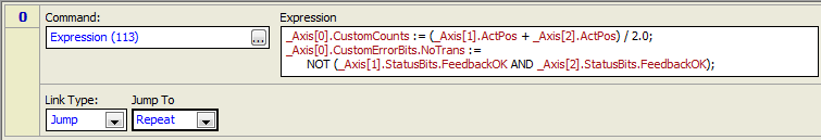
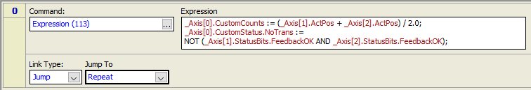
Below is a method using the Custom No Transducer Error bit. In this example, Axis 0 is the control axis with custom feedback. The feedback is calculated as the average position of the Axis 1 and Axis 2 reference axes. If the transducer of either reference axis receives an error, its Feedback OK status bit will turn off and the control axis' Custom No Transducer Error bit will be set. As soon as the errors in the reference axes clear, the Custom No Transducer Error bit will also clear, allowing the axis to perform closed-loop motion.
RMC75 and RMC150:
RMC200:
Custom Feedback Auto-Fault Mode
The Custom Feedback Auto-Fault Mode axis parameter defines certain cases in which the No Transducer or Prs/Frc No Transducer error bit will automatically be set. The following options are available:
Missed Update (default setting)
If the Custom Counts register is not written to in a given loop time, the No Transducer error will be set. This is the preferred mode for most applications. In this mode, you should make sure that the Custom Counts register is written to each loop time.
PROGRAM Mode
If the controller is in PROGRAM mode, the No Transducer error will be set. This mode may be useful in situations where you do not need to update the Custom Counts very often, but you do wish to halt the axis if the program that updates the Custom Counts is stopped due to the controller entering PROGRAM mode.
Disabled
The No Transducer error will not be set by any of the above options. In this mode, the updating of the Custom Counts register is not monitored in any way. This could be used in cases where the Custom Counts register is being modified from an external device, such as a PLC.
Additional Error Handling Considerations
In certain Custom Feedback applications cases, such as switching feedback on the fly, it may be normal for one of the reference axes to receive a transducer error. If you want the user programs to continue operating, make sure the tasks do not stop when the reference axis halts due to the error. This can be set in the Programming Properties, on the Halts page.
See Also
Switching Feedback using Custom Feedback | Feedback Linearization using Curves | Feedback Linearization using Mathematical Formula | Redundant Feedback using Custom Feedback
Copyright © 2026 Delta Computer Systems, Inc. dba Delta Motion