Open topic with navigation
PROFIBUS
Mode: Enhanced
The Enhanced mode is one of the Basic/Enhanced
PROFIBUS Modes available only on the RMC75P. Most users will prefer
the I/O Modes instead.
Features
This mode has the following features:
-
Eight (8) user-selectable cyclic read registers are continuously read for instant access by the PLC or PC.
See Response Block and Setting Up the Indirect Data Map below.
-
One (1) register anywhere in the RMC75 can be explicitly written or read.
See Read Any Single RMC75 Register and Write to Any Single RMC75 Register below.
-
Seven (7) contiguous registers in the RMC75 can be explicitly written or read.
See Read Any Contiguous RMC75 Registers and Write to Any Contiguous RMC75 Registers below.
-
Commands can be issued to any number of axes simultaneously.
See Command Block, Issue a Single Command, and Issue Simultaneous Commands below.
-
PROFIBUS bandwidth used: 2 blocks each of 16 I/O words (16 bits each).
RMC75 Register Addresses for PROFIBUS
When communicating over PROFIBUS, the RMC75
registers addresses use the same file:element addresses as the RMC75
IEC-61131
addresses.
For example, to read the Axis 0 Actual Position
via PROFIBUS, notice that its address is %MD8.8. Therefore, the address
via PROFIBUS is file 8, element 8.
Parameterization
Enhanced mode requires the PROFIBUS configuration
and parameterization listed below. The GSD file does direct the PROFIBUS
master setup software to automatically set up these values, but Delta
has found several cases where it is not supported correctly or manual
setup is otherwise required.
Configuration: FF
FF
Parameters:
Prm_Data (bytes
1-7): See the PROFIBUS DP specification for details.
User_Prm_Data (bytes
8-14): 00 00 00 xx* 01 08 08
* The xx parameter
can be 00 or 01 and selects whether the least-significant word comes first
(00) or most-significant word comes first (01).
Data Blocks
The Enhanced mode uses two fixed-length blocks
of data: the Command Block and
the Response Block.
 Command
Block
Command
Block
The Command block is a block of 16 contiguous 32-bit output registers. These registers are sent from the PLC or PC to the RMC.
The Command Block has the following structure:
|
Register
Number
|
Data
Type
|
Description
|
|
Command Area:
Registers 0 - 5 are used for issuing commands to the RMC75.
See Issue a Single Command
and Issue Simultaneous Commands
below for details on using these registers.
|
|
0
|
Integer
|
Command Register
|
Bit
|
Bit
Description
|
|
31
|
Command Request
|
|
30
|
Deferred Command
|
|
29
|
Deferred Command
|
|
20-28
|
Reserved
|
|
19
|
Axis 3 Select
|
|
18
|
Axis 2 Select
|
|
17
|
Axis 1 Select
|
|
16
|
Axis 0 Select
|
|
8-15
|
Reserved
|
|
7-0
|
Command Number
|
|
|
1
|
Float
|
Command Parameter 1
|
|
2
|
Float
|
Command Parameter 2
|
|
3
|
Float
|
Command Parameter 3
|
|
4
|
Float
|
Command Parameter 4
|
|
5
|
Float
|
Command Parameter 5
|
|
Data Channel 0:
Registers 6 and 7 are used for reading and writing to any register
in the RMC75. See Read
any Single RMC75 Register and Write
to any Single RMC75 Register for details on using these
registers.
|
|
6
|
Integer
|
Read/Write Register
|
Bit
|
Bit
Description
|
|
31
|
Read/Write
|
|
30
|
Read/Write Request
|
|
16-29
|
Reserved
|
|
15-8
|
R/W Address File
|
|
7-0
|
R/W Address Element
|
|
|
7
|
Float*
|
Explicit Write Value
|
|
Data Channel 1:
Registers 8-15 are used for explicit reads and writes. See
ReadAny
Contiguous RMC75 Registers and Write
Any Contiguous RMC75 Registers below.
|
|
8
|
Integer
|
Read/Write Command Register
|
Bit
|
Bit
Description
|
|
31
|
Read/Write
|
|
30
|
Read/Write Request
|
|
24-29
|
Reserved
|
|
16-23
|
Count
|
|
15-8
|
R/W Address File
|
|
7-0
|
R/W Address Element
|
|
|
9
|
Float*
|
Explicit Write Value 0
|
|
10
|
Float*
|
Explicit Write Value 1
|
|
11
|
Float*
|
Explicit Write Value 2
|
|
12
|
Float*
|
Explicit Write Value 3
|
|
13
|
Float*
|
Explicit Write Value 4
|
|
14
|
Float*
|
Explicit Write Value 5
|
|
15
|
Float*
|
Explicit Write Value 6
|
*These registers are typically REAL data type (floating point), but in some cases may be DINT or DWORD integers, such as variables declared as such.
Response
Block
The Response Block is a block of 16 contiguous 32-bit input registers (cyclic read registers). Registers 0-7 correspond to the Indirect Data Map registers 0 to 7 in the RMC75. These registers are continuously sent from the RMC to the PLC or PC. Registers 8-15 are for explicit reads or writes.
The Response Block has the following structure:
|
Register
Number
|
Data
Type
|
Description
|
|
Note:
Register 0 supplies the reading and writing acknowledge for
the Command Block register 6.
Note:
Registers 0-7 are consistent.
See explanation below.
|
|
0
|
Integer
|
Indirect Data 0 -
must
be mapped to Axis 0 Status bits!
|
Bit
|
Bit
Description
|
|
31
|
Command Acknowledge
|
|
30
|
Read/Write Acknowledge
|
|
0-29
|
Axis 0 Status Bits
|
|
|
1
|
Float*
|
Indirect Data 1
|
|
2
|
Float*
|
Indirect Data 2
|
|
3
|
Float*
|
Indirect Data 3
|
|
4
|
Float*
|
Indirect Data 4
|
|
5
|
Float*
|
Indirect Data 5
|
|
6
|
Float*
|
Indirect Data 6
|
|
7
|
Float*
|
Indirect Data 7
|
|
Note:
Register 8 supplies the reading and writing acknowledge for
registers 9-15.
|
|
8
|
Integer
|
Read/Write Acknowledge Register
|
Bit
|
Bit
Description
|
|
30
|
Read/Write Acknowledge
|
Note:
The entire Command Register 8 is echoed to this Read/Write
Acknowledge Register. Typically, bit 30 is the only bit used.
|
|
9
|
Float*
|
Explicit Read Data 0
|
|
10
|
Float*
|
Explicit Read Data 1
|
|
11
|
Float*
|
Explicit Read Data 2
|
|
12
|
Float*
|
Explicit Read Data 3
|
|
13
|
Float*
|
Explicit Read Data 4
|
|
14
|
Float*
|
Explicit Read Data 5
|
|
15
|
Float*
|
Explicit Read Data 6
|
*These registers are typically REAL data type (floating point), but in some cases may be DINT or DWORD integers, such as variables declared as such.
Consistent and Non-Consistent Registers
Registers 0-7 of the Response Block are consistent. That is, they are all updated at the same time. These registers are suitable for tight synchronization with the commands, read/write requests, or each other.
Registers 8-15 of the Response block are non-consistent. That is, each register is not guaranteed to be updated at the same time as the other registers in the block, nor at the same time as the registers in the first Response Block. They are updated at the same rate as the first Response block, but each register's update may differ slightly.
Because they are non-consistent, registers 8-15 should not be used for tight synchronization. The following registers should not be placed in Indirect Data Map registers 8 to 15 so that they will not be in registers 8-15 of the Response Block:
Configuring the Data
Setting
up the Indirect Data Map
The Response Block continuously returns the values from the RMC75 Indirect Data registers 0-7. These registers, in turn, can be mapped to any registers in the RMC75. Thereby, the values from the selected registers in the RMC75 can be read from and written to by writing to and reading from the Indirect Data registers.
To set up the Indirect Data Map:
-
In the Project pane, double-click Address Maps, then click Indirect Data Map.
-
In the Register column of the first Indirect Data Map entry, type "%MD8.0" and press Enter. This will map Axis 0 Status Bits register to the first item in the Indirect Data Map. Basic mode requires that the first item in the Indirect Data Map contains the Axis 0 Status Bits register.
-
For each of the remaining Indirect Data Map entries 1-7, enter the desired register to map to each. To do this, click the cell in the Register column, click the ellipsis button ( ), then browse to the desired register.
-
If you wish to add additional read capability, one of the Indirect Data Map registers should be mapped to the Read Response register. Then, the corresponding register in the Response Block will return the value of a read from any single register in the RMC75 at any time. See Read any Single RMC75 Register below. Notice that this is probably unnecessary because this mode already enables you to read from seven contiguous registers. See Read any Contiguous RMC75 Registers below.
Example
Requirements
The user would like to read the following registers:
-
Axis 0 Status Bits
-
Axis 0 Actual Position
-
Axis 1 Status Bits
-
Axis 1 Actual Position
-
Task 0 Current Step
-
Task 1 Current Step
In addition, the user would like to read some other registers occasionally.
Implementation
-
First, PROFIBUS communications requires that Axis 0 Status Bits register must be in the first Response Block register, which is entry 0 in the Indirect Data Map.
-
Second, the Read Response register is needed in order to read other registers occasionally.
-
Third, the rest of the registers listed above can be put anywhere in the remaining Indirect Data Map registers 0-7.
The user chose to set up the Indirect Data Map like this:
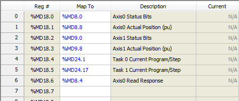
Using the Data Blocks
Issue
a Single Command
To issue a command, set up the contents of the first six registers of the Command Block, and when complete, toggle the Command Request bit in the first Command Block register.
Notice that commands with more than 5 command parameters cannot be issued via PROFIBUS. To issue such commands, include them in a user program and issue a command via PROFIBUS to start the user program.
To issue a single command to the RMC75, use the following steps:
-
Wait until the Command Request bit in the Command Register (0) of the Command Block is equal to the Command Acknowledge bit in register 0 of the Response Block. If they are not equal, the RMC is currently processing a command request.
-
Enter the command number in bits 0-7 of the Command Register (0) of the Command Block.
-
If the command has any parameters, put them in registers 1-5 of the Command Block.
-
Clear the Deferred Command bits.
-
Set the desired Axis Select bit in the Command Register. The command will be sent simultaneously to each axis you select.
Note:
Using this method, you can send a single command to multiple axes simultaneously. You cannot send different commands to multiple axes simultaneously. To send different commands to multiple axes simultaneously, see the Issue Simultaneous Commands section below.
-
Toggle the Command Request bit.
-
Wait until the Command Request bit is equal to the Command Acknowledge bit. When they are equal, the RMC75 has received the command.
NOTE:
Until the Command Acknowledge bit matches the Command Request bit, the Input Data registers, including the Status Bits registers, do not reflect having received the command.
Example
A Move Absolute (20) command is issued using the PROFIBUS Command Block. Until the Command Request bit matches the Command Acknowledge bit after the Command Request bit has been toggled, the In Position bit should not be checked as it may still be set for the previously requested move. Once the Acknowledge toggles to match, the In Position bit will have been cleared and when it is set, it is due to the new command being complete. Similar synchronization issues are resolved in the same way with other status bits and registers.
Issue Simultaneous Commands
Although only one command may be sent at a time to the RMC75P via PROFIBUS, it is possible to simultaneously issue different commands to several axes by using deferred commands. Deferred commands are stored in the PROFIBUS command buffer until all deferred commands are received. They are then executed simultaneously. Bits 30 and 29 in the Command Data Register of the Command Block define the deferred status of each command issued. The bits are used as follows:
|
Bit
30
|
Bit
29
|
Action
|
|
0
|
0
|
Single Command: When both
bits are zero, the command is not deferred. The command is
executed normally. If the PROFIBUS command buffer contains
any commands, an error is logged in the Event Log and the
commands are removed from the command buffer without being
executed. The new command is still issued.
|
|
0
|
1
|
Last Deferred: This command
and any deferred commands in the PROFIBUS command buffer are
executed simultaneously.
|
|
1
|
0
|
First Deferred: This command
is placed as a deferred command in the PROFIBUS command buffer,
but is not otherwise processed. If the command buffer
already contains commands, an error is logged in the Event
Log and the commands are removed from the command buffer without
being executed. The new deferred command is still placed
in the command buffer.
|
|
1
|
1
|
Middle Deferred: This command
is placed as a deferred command in the PROFIBUS command buffer,
but is not otherwise processed. This deferred command
type allows other deferred commands to be in the command buffer,
although they are not required to be there. Note that
for a 2-axis controller, this deferred setting will not be
used because there can only be a first and last deferred command.
|
Multiple deferred commands cannot be issued to the same axis. That is, if a deferred command is issued to an axis that already has a deferred command, an error is logged in the Event Log and the previous command is overwritten without being executed.
Read
Any Single RMC75 Register
Registers 0-7 of the Response Block return the values from 8 registers, which must be determined when setting up the communications. However, it is possible to set up one of the registers 1-7 in the Response Block to return the value of a read from any single register in the RMC75.
When a read is requested from any single register in the RMC75, the response from this single-register read will be placed in the Axis 0 Read Response register. In order to see the response from the PROFIBUS, you must map the Axis 0 Read Register into one of the Indirect Data Map registers.
Notice that the copy from the requested register into the Axis 0 Read Response register only occurs once, and therefore you will not see the value continuously updating like the other Response Block registers.
To read any single register from the RMC75, use the following steps:
-
Wait until the Response Block register 0 Read/Write Request bit is equal to the Command Block register 6 Read/Write Acknowledge bit. If they are not equal, the RMC75 is currently processing a read or write request.
-
Clear the Command Block register 6 Read/Write bit.
-
Set the Command Block Register 6 Read/Write Address File and Read/Write Address Element. For example, for address %MD8.12, the file is 8, and the element is 12. For a description of all RMC75 registers and their addresses, see the RMC75 Register Map topic.
-
Toggle the Read/Write Request bit.
-
Wait until the Read/Write Request bit is equal to the Read/Write Acknowledge bit. When they are equal, the RMC75 will have updated the Axis 0 Read Response register with the requested data, and the corresponding Response Block register.
To further clarify the ordering, keep these basic rules in mind:
-
Do change the read address and Read/Write bit before toggling the Read/Write Request bit.
-
Do not change the Read/Write Request bit after a read request until you have processed the data in the Read Response register.
-
Do not change the read address or Read/Write bit when the Read/Write Request bit does not match the Read/Write Acknowledge bit.
Read
Any Contiguous RMC75 Registers
To read any contiguous RMC75 registers, use the Command Block register 8 and the Response Block registers 8-15.
To read any contiguous RMC75 registers, use the following steps:
-
Wait until the Command Block register 8 Read/Write Request bit is equal to the Response Block register 8 Read/Write Acknowledge bit. If they are not equal, the RMC is currently processing a read or write request.
-
Clear the Command Block register 8 Read/Write bit.
-
In the Command Block register 8, set the Read/Write Address File and Read/Write Address Element to the first RMC75 address you wish to read. For example, for address %MD8.12, the file is 8, and the element is 12. Set the Count to the number of register to read, up to 7. For a description of all RMC75 registers and their addresses, see the RMC75 Register Map topic.
-
Toggle the Read/Write Request bit.
-
Wait until the Read Request bit is equal to the Read/Write Acknowledge bit. When they are equal, the RMC75 will have updated the Response Block registers 8-15 with the requested data.
To further clarify the ordering, keep these basic rules in mind:
-
Do change the read address and Read/Write bit before toggling the Read/Write Request bit.
-
Do not change the Read/Write Request bit after a read request until you have processed the data in the Read Response register.
-
Do not change the read address or Read/Write bit when the Read/Write Request bit does not match the Read/Write Acknowledge bit.
Write
to Any Single RMC75 Register
To write to a single RMC75 register, use the Command Block register 6 and the Response Block register 0. Register 0 of the RMC75 Indirect Data Map must be mapped to the Axis 0 Status Bits register.
To write to the RMC75, use the following steps:
-
Wait until the Command Block register 6 Read/Write Request bit is equal to the Response Block register 0 Read/Write Acknowledge bit. If they are not equal, the RMC75 is currently processing a read or write request.
-
Copy the value you wish to write to the RMC75 into the Write Value register (7) of the Command Block.
-
In the Command Block register 6, enter the Read/Write Address file and element. For example, for address %MD56.0, the file is 56, and the element is 0. For a description of all RMC75 registers and their addresses, see the RMC75 Register Map topic.
-
Set the Command Block register 6 Read/Write bit.
-
Toggle the Read/Write Request bit.
-
Wait until the Read/Write Request bit is equal to the Read/Write Acknowledge bit. When they are equal, the RMC75 has received the data written to it.
To further clarify the ordering, keep these basic rules in mind:
-
Do change the Read/Write bit, write address, and write value before toggling the Read/Write Request bit.
-
Do not change the Read/Write bit, write address, or write value when the Read/Write Request bit does not match the Read/Write Acknowledge bit.
Note:
The RMC75 sets the Read/Write Acknowledge bit equal to the Read/Write Request to the acknowledge that the write was processed. In addition, the RMC75 also places the write value in the Read Response register. This provides a simple method of verifying that the write was completed.
Write
to Any Contiguous RMC75 Registers
To write to any contiguous RMC75 registers, use Command Block registers 8-15 and Response Block register 8. To write to the RMC75, use the following steps:
-
Wait until the Command Block register 8 Read/Write Request bit is equal to the Response Block register 8 Read/Write Acknowledge bit. If they are not equal, the RMC75 is currently processing a read or write request.
-
Set the Command Block register 8 Read/Write bit.
-
In the Command Block register 8, set the Read/Write Address File and Read/Write Address to the first RMC75 address you wish to write to. Set the Count to the number of register to write, up to 7. For a description of all RMC75 registers and their addresses, see the RMC75 Register Map topic.
-
In the Command Block registers 9-15, put the values you wish to write.
-
Toggle the Read/Write Request bit.
-
Wait until the Read/Write Request bit is equal to the Read/Write Acknowledge bit. When they are equal, the RMC75 has received the data written to it.
To further clarify the ordering, keep these basic rules in mind:
-
Do change the Read/Write bit, write address, and write value before toggling the Read/Write Request bit.
-
Do not change the Read/Write bit, write address, or write value when the Read/Write Request bit does not match the Read/Write Acknowledge bit.
Debugging
Using
the Event Log for PROFIBUS
The Event Log can record every change in the PROFIBUS data received by the RMC75P. This is the data in the Command Block. It does not record the data in the Response Block, which is sent by the RMC75P. The Event log displays the received data in hexadecimal format.
The Event Log can log an entry when any of the following occurs:
-
Data is Initialized
(the Configuration Information box must be checked in the Event Log filter for PROFIBUS)
This typically occurs when the RMC75 is restarted. The Event Log entry will be labeled initial data. It provides the user with a reference of what the initial data is.
For example, assume a user wrote a 1 to the Command Request bit to issue a command immediately after starting the PROFIBUS communications, but the command was not issued. The user then looked in the Event Log and found out that the initial data showed that the Command Request bit already was 1, which explains why the command was not issued. The bit must be toggled to send a command, so he should have written a 0.
-
Data Changes
(the Command Channel Logging and Data Channel Logging boxes must be set to All in the Event Log filter for PROFIBUS)
Each time the data in the Command Block changes, the data will be logged with an entry labeled changed. The entry will also specify which data changed, as described below.
-
A Request is Made
(the Command Channel Logging and Data Channel Logging boxes must be set to All or Requests in the Event Log filter for PROFIBUS)
Each time a Command Request bit or Read/Write Request bit is toggled, the entry will be labeled request made. This indicates a command was requested to be issued, or a read or write was made.
Tip:
In some cases, a request can be made, but nothing happens. This is probably caused by one of the following:
- A command was requested, but no Selected Axis bit was set.
- A read or write of multiple registers was requested, but the Count was set to 0.
The Event Log labels the logged entries in the following manner:
-
Command Area
These 6 registers are the data used to issue commands to the RMC75.
-
Data Channel 0
These 2 registers contain the data for reading or writing a single RMC75 register.
-
Data Channel 1
These 8 registers contain the data for reading or writing to contiguous RMC75 registers.
Debugging the Command Area Data
The Event Log displays the Command Area data in the following order:
Cmd Register, Cmd Parameter 1, Cmd Parameter 2, Cmd Parameter 3, Cmd Parameter 4, Cmd Parameter 5
Example:
Assume a Move Absolute command has been issued to the RMC75 via PROFIBUS. The Event Log may look like this:
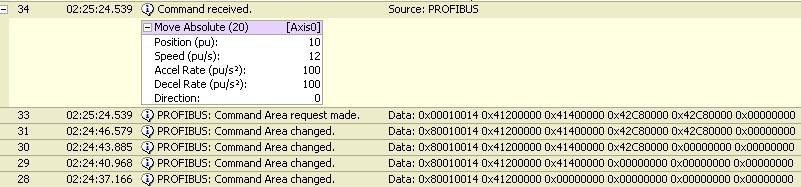
Steps 28-31 show how the command parameters are changing. The command word shows the command that will be issued, (hexadecimal 14 is 20 in decimal), and the command select bit ( the 1 in the middle of the word).
In step 33, bit 31 of the Command Register changed, which then issued the move command.
Debugging Data Channel 0
The Event Log displays the Data Channel 0 data in the following order:
Read/Write Register (register 6), Explicit Write Value (register 7)
Example:
Assume a value of 46.2 was written to %MD56.0 via PROFIBUS. The Event Log may look like this:

Step 38 shows that the File is 56 (38 in hexadecimal), bit 31 is set to 1 for a write. The Explicit Write register contains the write value 46.2, but it is very difficult to decipher a float value from its hexadecimal representation.
Step 39 shows that the Read/Writer Request bit changed, which requested the write.
Debugging Data Channel 1
The Event Log displays the Data Channel 1 data in the following order:
Read/Write Command Register (register 8), Explicit Write Value 0, Explicit Write Value 1, Explicit Write Value 2, Explicit Write Value 3, Explicit Write Value 4, Explicit Write Value 5, Explicit Write Value 6
Example:
Assume 3 values were written to 3 registers beginning at %MD56.10. The Event Log may look like this:
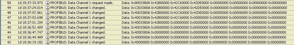
In step 43, the Element is 10 (A in hexadecimal).
In step 44, the File is set to 56 (38 in hexadecimal).
In step 45, the count is set to3.
In steps 46 to 48, the write values are entered.
In step 49, bit 31 is set to 1 for a write.
In step 50, bit 30 is toggled to request the write.
See Also
Basic/Enhanced
PROFIBUS Modes | PROFIBUS
Configuration | PROFIBUS-DP
Overview
Send comments on this topic.
Copyright © 2026 Delta Computer Systems, Inc. dba Delta Motion