The RMC's PROFIBUS I/O modes continuously pass blocks of data between the PLC and RMC. The following modes are available on the RMC150E and RMC75P:
I/O Mode (4 registers)
I/O Mode (8 registers)
I/O Mode (16 registers)
I/O Mode (32 registers)
Each of these modes specifies a number of 32-bit registers, n. For each mode, n registers are continuously sent from the RMC's first nIndirect Data Map registers, and n registers are always sent from the PLC to the first n registers in the RMC's Variable Tables.
For your application, choose the mode with the number of registers you need. The PROFIBUS I/O modes are very simple and easy to use. No handshaking is required, and you are free to use the data as you wish. The PROFIBUS data is updated each Loop Time of the RMC.
Put in other words, the PLC's PROFIBUS Input Data comes from the RMC's Indirect Data Map, and the PLC's PROFIBUS Output Data goes to the RMC's Variable Tables.
The RMC's Indirect Data Map is an area in which any register in the RMC can be mapped to. Therefore, to have the PLC read any register in the RMC via one of the I/O modes, just put it in the Indirect Data Map.
The RMC's Variable Table contains variable registers that can be used for any purpose. Writing to these variables via the I/O modes can do such things as changing settings or profiles, or starting user programs.
The I/O data is consistent. A block of PROFIBUS data is called 'consistent' if it is consistent over the length of the block, rather than just over a single 8- or 16-bit data item. Consistent blocks of data will stay together through the communication, from the time it was captured in one device until it is delivered to the other device, whereas data from different consistent blocks could have been sampled at different times.
The I/O modes require firmware version 3.10 or newer.
Parameterization
The I/O modes require the PROFIBUS configuration and parameterization listed below. The GSD file directs the PROFIBUS master setup software to automatically set up these values, but Delta has found several cases where it is not supported correctly or manual setup is otherwise required.
|
I/O Mode: |
32 registers |
16 registers |
8 registers |
4 registers |
|
Configuration |
C0 FF FF |
C0 DF DF |
FF |
F7 |
|
Parameters (bytes 1-7) (Prm_Data) |
See the PROFIBUS DP specification for details. |
|||
|
Parameters (bytes 8-13) (User_Prm_Data) |
00 00 00 xx* 02 20 |
00 00 00 xx* 02 10 |
00 00 00 xx* 02 08 |
00 00 00 xx* 02 04 |
* The xx parameter can be 00 or 01 and selects whether the least-significant word comes first (00) or most-significant word comes first (01).
Notice that some masters will not support the larger I/O modes.
Using the I/O Modes
1. Configure the PROFIBUS communications
Configure the PROFIBUS communications as described in the PROFIBUS configuration topic.
2. Set up the Indirect Data Map
Once you have chosen the mode and configured the PROFIBUS communications, you will need to set up the RMC's Indirect Data Map for the data you wish to continuously send to the PLC. For details, see the Indirect Data Map topic.
Keep in mind that the first n registers of the Indirect Data Map will continuously be sent to the PLC.
Example
A user decides to use I/O Mode (4 regs). This means that the first four items of the Indirect Data Map will continuously be sent to the PLC. The user wants the PLC to monitor the following:
Axis 0 Status bits
Axis 0 Actual Position
Task 0 Status
Task 0 Current Program
Therefore, the user would add these items to the Indirect Data Map. The Indirect Data Map editor will then look like this:
It is important to check the External Data Types of the registers used in the register map, and treat them accordingly in the master controller.
3. Set Up the Variable Table
The PLC's Output Data will be continuously sent to the first n registers in the RMC's Variable Table. You should add tag names to each data item and make sure the Data Type is set correctly.
Example
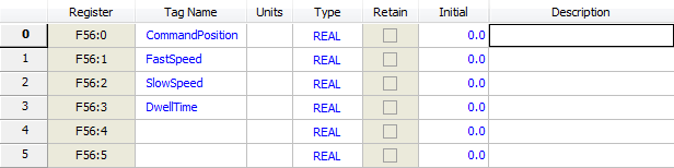
A user decides to use I/O Mode (4 regs). This means that the PLC's Output Data will consist of four registers that will be continuously sent to the first four items in the RMC's Variable Table. The user wants the PLC to send the following four data items to the RMC:
Command Position (REAL Data Type)
FastSpeed (REAL Data Type)
SlowSpeed (REAL Data Type)
DwellTime (REAL Data Type)
Therefore, the user sets the tag names and Data Types of the first four items in the Variable Table like this:
4. Perform Communications
After configuring the PROFIBUS and setting up the Indirect Data Map and Variable Table, start the PROFIBUS communications. Once the PROFIBUS connection is established, the RMC's Indirect Data Map registers will continuously be sent to the PLC's Input Data, and the PLCs' Output Data will continuously be sent to the RMC's Variable Table. The RMC's variables can be used for anything that they normally are used for. However, trying to change the PROFIBUS variables from user programs is not very useful, because the variables will be overwritten by the PROFIBUS.
Issuing Commands via I/O Mode
To issue commands, or write to RMC registers (other than the I/O Mode variables), or do anything else via the I/O modes, you must create a user program. You can then use the Program Triggers to start a user program when an I/O Mode variable becomes a certain value.
To program the RMC to do this, you must:
Create user programs to do the desired actions.
Define a variable for starting the programs.
Edit the Program Triggers to start the user programs based on the value of the variable.
Example
Bruce is using I/O Mode (8 regs). He wants to run two different user programs on the machine. The first program will move back and forth once, and the second will move to a home position. The PLC will send the two cycle positions, the speed, and the home position to the RMC.
Bruce defines variable zero as StartProgram, and defines 4 more variables for his cycle positions, speed, and home position.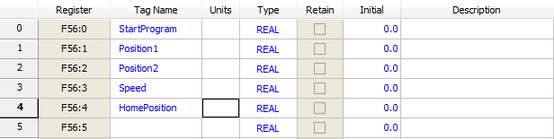
Bruce creates the user programs and calls them Cycle and MoveHome: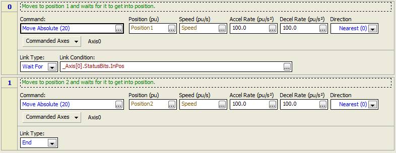
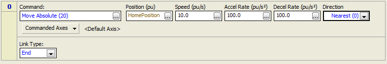
Bruce edits the Program Triggers to start the Cycle program when StartProgram is 1, and to start the MoveHome program when StartProgram is 2.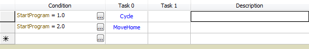
Now Bruce is ready to perform the communications. To run the Cycle program, the PLC first sets up the position and speed variables, then sets the StartProgram variable to 1. To run the program again, the PLC must first set the StartProgram variable to some other number (such as 0), then set it to 1.
To run the MoveHome program, the PLC must first set the HomePosition variable, then set the StartProgram variable to 2.
Handshaking
The I/O Modes do not require any handshaking, but you may wish to make some simple handshaking so the PLC knows the RMC is running normally and is performing the requested actions. Here are some methods of doing simple handshaking:
Put the StartProgram Variable in the Indirect Data Map
In the example above, the StartProgram variable could be put in the Indirect Data Map, so the PLC could see that it changed correctly and knows the communications is working properly.
Use the Task Status Registers.
The Task status registers indicate whether a task is running, and which user program it is running. You can add these registers to the Indirect Data Map so the PLC can see if the correct user program is running.
Create a Program Done Variable
You can create a variable for reporting when a user program is complete. For example, at the beginning of the user program, add a step with an Expression (113) command that sets the variable to zero. Then, at the end of the user program, add a step with an Expression (113) command that sets the variable to a certain number indicating that the user program is complete. Make sure to include this variable in the Indirect Data Map so the PLC can see it.
See Also
Copyright © 2026 Delta Computer Systems, Inc. dba Delta Motion