Command: Curve Start Advanced (88)
See the Commands
Overview topic for basic command information and how to issue commands
from PLCs, HMIs, etc.
Command Parameters
|
#
|
Parameter Description
|
Data Type
|
Range
|
|
1
|
Curve ID
|
Internal: DINT
External: REAL
|
0-50000
|
|
2
|
Master Register
Note: See Specifying a Register Address below.
|
REAL
|
_Time or any other valid register of type REAL.
|
|
3
|
Cycles
0 = continuous,
1 = 1 cycle
n=n cycles (up to 16 million)
|
REAL
|
0 to 16 million
(0 = continuous)
|
|
4
|
Options, sum of the following:
Curve Alignment, one of:
Absolute Curve Alignment (+0)
Relative Curve Alignment (+1)
Master Alignment, one of:
Relative Master Alignment (+0)
Absolute Master Alignment (+2)
Endpoint Behavior
For Absolute Master alignment, one of:
Fault (+0)
Truncate (+4)
Extrapolate (+8)
For Relative Master alignment, one of:
Standard (+0)
Truncate (+4)
Truncate and End (+8)
|
Internal: DINT
External: REAL
|
≥ 0, whole numbers
|
|
5
|
Curve Scale
|
REAL
|
any
|
|
6
|
Curve Offset
|
REAL
|
any
|
|
7
|
Master Scale
|
REAL
|
≠ 0
|
|
8
|
Master Offset
|
REAL
|
any
|
|
9
|
Status Block (address)
Note: See Specifying a Register Address below.
|
REAL
|
Address or
none(0)
|
Description
This command is identical to the Curve
Start (86) command, but with additional advanced options such as offsetting
or scaling the y-axis of the curve, offsetting or scaling the curve master,
choosing absolute or relative curve alignment or master alignment, and
the inclusion of a status block for advanced status information.
Notice that the command parameters do not change
the curve itself in the RMC. It only defines the instance of the curve
that is started with this command.
This topic describes only the advanced features
of this command. For basic information on using this command, see the
Curve Start (86) command.
Absolute/Relative Curve Alignment
Curve alignment refers to the Y-values of the
curve, which are the positions of the curve axis:
Absolute
With Absolute
curve alignment, the positions will be exactly as defined by the curve.
To choose absolute curve alignment, add +0 to the Options
command parameter.
Relative
With Relative
curve alignment, the Y-values will be relative to the Target Position
of the curve axis at the time the Curve Start Advanced command is sent.
That is, the Y-values in the Curve
Data will be adjusted such that the Point 0 Y-value is set to the
current position of the axis. All the other Y-value points will be adjusted
by the same amount. To choose relative curve alignment, add +1 to the
Options command parameter.
Transitions
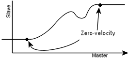
When using absolute curve alignment, the axis
must be at the correct point in the curve when the Curve Start Advanced
command is issued. The correct point can be very difficult to determine
if the master is not at the starting point, and therefore, the Transition
Rate (56) command must be used to specify how the axis should get
to the correct point when this command is issued.
Absolute/Relative Master Alignment
Master alignment refers to the X-values of the
curve, which are the positions of the master:
Absolute
With Absolute
master alignment, the x-values will be exactly as defined by the curve.
To choose absolute master alignment, add +2 to the Options
command parameter.
Absolute master alignment
is intended for applications where the curve must occur at an exact location
based on the position of the master, such as in camming.
Relative
With Relative
master alignment, the X-values will be relative to the master value at
the time the Curve Start Advanced command is sent. That is, the X-values
in the Curve
Data will be adjusted such that the Point 0 X-value is set to the
current value of the master. All the other X-value points will be adjusted
by the same amount. To choose relative master alignment, add +0 to the
Options command parameter.
Relative master alignment
is intended for applications where the starting master point of the curve
may vary, which may be the case when the master is a conveyor belt or
a feed chain, such as in curve sawing. The Endpoint Behavior options
for a relative master are specifically designed for this type of use case.
Using _Time as an Absolute Master
The _Time register wraps every second through
the range [0.000000, 1.000000). It can be used as a master for curves
that are to run based on time. When using _Time as an absolute master,
the _Time is assumed to be zero when the Curve Start Advanced command
is issued. Using a Master Offset will adjust the curve in time, effectively
delaying the curve, or beginning at some point in the middle of the curve.
Endpoint Behavior
The Endpoint Behavior specifies what happens
to the curve axis if the master moves outside of the X-value range defined
by the curve data. For cyclic curves, the endpoints are the beginning
of cycle 0, and the end of the last cycle. Infinite cyclic curves will
continue until another motion command is issued to the axis.
Endpoint Behavior with Absolute Master Alignment
The
Endpoint Behavior options listed below apply when Absolute Master Alignment
(+2) is selected. The axis is assumed to be in the first cycle when this
command is issued.
|
Option
|
Description
|
Image
|
|
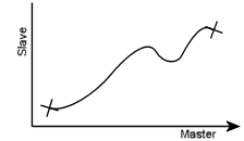
Fault (+0)
|
If the master exceeds either endpoint, the curve axis' runtime error bit will be set which will halt the axis according to the Auto Stops setting for the Runtime error.
|

|
|
Truncate (+4)
|
If the master moves past an endpoint, the curve axis' Target Position will stop at the endpoint. When the master moves back into the range, the curve will resume. If the master is moving quickly when it exceeds the endpoint, it may cause the curve axis to stop abruptly.
|

|
|
Extrapolate (+8)
|
The curve will be extrapolated linearly, using the Target Velocity at the endpoint of the curve. When the master moves back into the range, the curve will resume.
|

|
Endpoint Behavior with Relative Master Alignment
The Endpoint Behavior options listed below apply
when Relative Master Alignment (+0) is selected.
|
Option
|
Description
|
Image
|
|
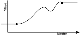
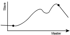
Standard (+0)
|
Curves with zero-velocity endpoints will follow the curve until the end is reached, or another motion command is issued. When the master register moves outside the range of the curve, the curve axis will remain stopped at the appropriate endpoint, unless master re-enters the curve by reversing direction.
Curves with Relative Master Alignment that end with non-zero velocity endpoints will continue for two loop times after the master moves beyond the starting or ending point. If another motion command is not issued within two loop times of the master moving beyond the starting or ending point, then a Closed Loop Halt will occur and the Runtime Error bit will be set. Notice that if the Runtime Error AutoStop is set to a halt, that halt will also occur. Use a Link Condition in a user program to check the Target Generator bits to determine whether the master has moved beyond the endpoints. See the Target Generator State Bits section below.
|
Zero-velocity endpoints:

Non-zero-velocity endpoints:

|
|
Truncate (+4)
|
If the master moves past the beginning or end, the curve axis' Target Position will stop at that point. When the master moves back into the range, the curve will resume. If the master is moving quickly when it exceeds the endpoint, it may cause the curve axis to stop abruptly.
|

|
|
Truncate and End (+8)
|
If the master moves past the end, the curve axis' Target Position will stop at the endpoint and the curve will stop executing. If the master moves back into the range, the curve will not resume. Notice that if the master moves past the beginning point, the curve will still continue executing when the master moves back in to the range.
If the velocity at the endpoint is non-zero, the velocity will abruptly go to zero.
|

|
Curve Scale and Offset
The Curve Scale
and Curve Offset parameters operate
on the Y-values of the curve. These parameters can be used to shift the
curve up or down in the y-axis, or compress or expand the curve in the
y-axis. For each Y-value of the curve, the new Y-value is calculated as
follows:
Ynew
= (Yoriginal x Curve Scale) + Curve Offset
The Curve Offset applies only to absolute curve
alignment. The Curve Scale applies to both absolute and relative curve
alignment.
Master Scale and Offset
The Master
Scale and Master Offset
parameters scale or shift the curve master. The X value used to index
into the curve is found using the following formula:
X = ( Master Value
+ Master Offset ) x Master Scale
This can also be viewed as shifting and expanding
or contracting the curve itself along the X axis. From that perspective,
the X value for each point is calculated as follows:
Xnew
= (Xoriginal ÷ Master Scale) - Master Offset
The Master Offset applies only to absolute master
alignment. The Master Scale applies to both absolute and relative master
alignment.
Status Block
Advanced users may wish to use the Curve Start
Advanced command's Status Block,
which provides read-only information on the curve motion. This information
is most useful when manipulating the curve in user programs.
To use the Status Block, you must specify an
address from the Variable Table in the Status
Block parameter of the Curve Start Advanced command. The Status
Block will require six registers in the Variable Table, beginning with
the specified address. As the curve motion progresses, the selected registers
in the Variable Table will be continuously updated. The selected variables
will not be named automatically; you should give a descriptive name to
each to help you keep track of them.
To prevent confusion, curves that are running
simultaneously should not use the same Status Block address. Non-simultaneous
curves can use the same Status Block address.
The Status Block provides the following information:
|
Status Block Offset
|
Name
|
Data Type
|
Description
|
|
0
|
Current Cycle
Count
|
REAL
|
The whole number of cycles of the curve that have been completed.
For continuous curves (without a fixed number of cycles), this value will wrap to zero after it reaches 10,000,000 and then continue incrementing. For curves with a fixed number of cycles, this value will not go beyond the requested cycle count.
|
|
1
|
Current Index
|
REAL
|
Indicates the current X value being used for interpolating through the curve. This value is in the original X scale and offset with which the curve was defined. This value will wrap for each cycle.
|
|
2
|
Current Curve Scale
|
REAL
|
The current Curve Scale of the curve.
|
|
3
|
Current Curve Offset
|
REAL
|
The current Curve Offset of the curve. This value is calculated automatically for the Relative Curve Alignment option.
|
|
4
|
Current Master Scale
|
REAL
|
The current Master Scale of the curve.
|
|
5
|
Current Master Offset
|
REAL
|
The current Master Offset of the curve. This value is calculated automatically for the Relative Master Alignment option.
|
Running a Curve Backwards
To run a curve backwards with a _Time master,
use Absolute Master Alignment, a Master Scale of -1, and a Master Offset
value that is equal to the X value of the last point of the curve.
Specifying a Register Address
When issuing this command from anywhere other
than RMCTools, the addresses in the Master
Register and Status Block
command parameter must be entered as an integer value.
RMC addresses are represented in IEC format
as:
%MDfile.element, where file
= file number, and element =
element number.
Use the following equation to convert a register
address to integer format, N:
N = file
* 4096 + element
Example:
Register address %MD8.33 is 8*4096 + 33 = 32801.
_Time:
The register address for the _Time tag in the
RMC75 is %MD20.10. Therefore, the value is 20*4096 + 10 = 81930.
The register address for the _Time tag in the
RMC150 is %MD44.10. Therefore, the value is 44*4096 + 10 = 180234.
The register address for the _Time tag in the
RMC200 is %MD18.10. Therefore, the value is 18*4096 + 10 = 73738.
Status Registers
The Cycles
axis status register gives the whole number of cycles that the current
curve has completed. After a curve
has completed or been interrupted, this will remain at its current
value. This value is reset each time the Curve Start Advanced command
is sent.
Status Bits
In Position Bit
The In Position bit will be set only in the
following cases:
-
For curves using _Time as the master register, the In Position bit will be set when the curve has completed.
-
For curves with a relative master alignment, and the Truncate and End (+8) option, the In Position bit will be set when the master has moved beyond the ending point of the curve.
Target Generator State Bits
The Target Generator bits in the Status
Bits register indicate which portion of the move the axis is currently
in. These bits are useful for determining whether the curve has reached
the starting or ending points.
Target Generator Done bit
Set when the master
position is at or beyond the ending point. Notice that for master-based
curves with a zero-velocity ending point, the curve is still being followed
(unless the Truncate and End option
has been selected and the master is beyond the ending point). That is,
if the master backs up into the curve, then the curve axis will resume
following the curve backwards, and the Target Generator Done bit will
be cleared.
Target
Generator State A and B bits
|
B
|
A
|
Description
|
|
0
|
0
|
The master is beyond (not at) the ending point.
|
|
0
|
1
|
The master is prior to (not at) the starting point.
|
|
1
|
0
|
The master is between the starting and ending points or at the starting or ending point.
|
|
1
|
1
|
Reserved.
|
Pri. TG SI Busy (Primary
Target Generator Superimposed Busy) Bit
This bit will be
set during the transition. The transition begins when the motion command
is issued, not necessarily when the Transition command is issued. When
the transition completes, this bit will clear.
See Also
Curves
Overview | Curve Start (86)
| Curve
Start Advanced (Prs/Frc) (89) | Curve
Data Formats | Change Master
(79)
Send comments on this topic.
Copyright © 2025 Delta Computer Systems, Inc. dba Delta Motion


