Position I-PD is an algorithm that can be used to perform closed-loop motion control on a position axis. I-PD stands for the central gains used in this mode: Integral, Proportional, and Differential. The "-" indicates how the algorithm uses these gains.
For most motion applications, the Position I-PD is not as well-suited as the Position PID. However, the Position I-PD differs from the Position PID in that it can easily be tuned so that it does not overshoot. The Position I-PD is therefore very suitable for applications where the Target Position jumps. An example is an axis geared to a reference input that makes discrete jumps. The Position I-PD typically does not respond as quickly and does not use Feed Forwards. Therefore, it will always lag behind the Target Position when moving.
Position I-PD Advantages
Easy to tune for minimal overshoot, making it excellent for controlling an axis that follows an irregular target, such as step jumps or a joystick.
Is not disrupted by a saturated Control Output.
Position I-PD Disadvantages
Not well suited for following a specific target profile.
Does not track position changes very quickly. May take longer to get into position.
Motion Commands in Position I-PD Mode
The following commands are designed for use only with Position I-PD and automatically put the axis into the Position I-PD control mode during the commanded motion:
Move Absolute (I-PD) (28)
This command immediately sets the target to the requested position. It does step-jump; it does not ramp it.
Move Relative (I-PD) (29)
This command immediately sets the target to the requested distance from the specified position (Target, Actual, or Command). It does step-jump; it does not ramp it.
To use the Position I-PD control mode with other motion commands, first use the Set Pos/Vel Ctrl Mode (68) command to set the Next Pos/Vel Control Mode to Pos I-PD. The next closed-loop motion command will use the control mode specified in the Next Pos/Vel Control Mode status register. The Current Control Mode register indicates the mode currently in use.
See the Closed Loop Control topic for details on which commands are supported in Position I-PD control.
Special Notes
Decreasing Jerk at Start of Motion
When using the Move Absolute (I-PD)(28) and Move Relative (I-PD)(29) commands, the system will start moving with a sudden jerk. This is because the Target Position is set to the Command Position immediately. In many systems this is acceptable. If it is not acceptable for your system, you can instead use the Move Absolute (20) or Move Relative (21) commands in I-PD mode. With these commands, the Target Position is ramped toward the Command Position at the speed you specify (set the Accel and Decel to a high value, such as 1000). This will essentially eliminate the sudden jerk. This may increase the time it takes to get into position at the end of the move.
Fast Moves (Saturating the Output)
If the Control Output saturates, the I-PD is not disrupted like the PID is (with the PID, the Integrator doesn't handle it very well). Therefore, the I-PD can be used to move the system at it's maximum speed (typically the speed at 10V Control Output). To achieve this, with the Move Absolute (I-PD)(28) and Move Relative (I-PD)(29) commands, set the Maximum Speed command parameter to a value greater than you system's maximum speed. The moves will then saturate the Control Output during the move, indicating that it is moving at it's maximum speed. You will, of course, need to set the Output Saturated Auto Stop to Status Only.
Saturating the output can be very useful with non-linear valves where the gain "rolls off" at the upper end. With a PID, it is especially difficult to get close to maximum speed, because a small increase in speed can suddenly saturate the output. The I-PD makes it easy to get to maximum speed.
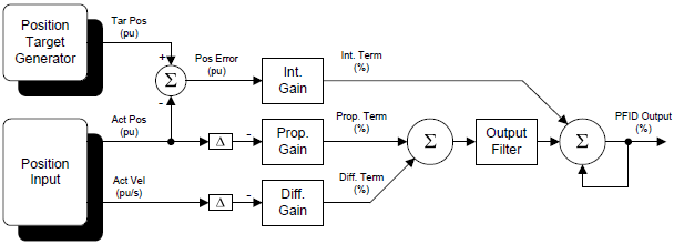
Position I-PD Algorithm
Each closed loop motion command issued to the RMC specifies a target profile, which defines where the axis should be at any given moment. For each loop time when the axis is in closed loop control, the Position I-PD algorithm calculates the values from each gain, as described below. Then, the terms from the Proportional and Differential gains are subtracted from the Integral Gain term. The resulting value (in percent) is multiplied by the maximum output (typically 10V), to come up with the Control Output voltage for that loop time.
Gains and Feed Forwards
The Position I-PD uses the gains listed below. It does not use any Feed Forwards.
Integral Gain
The Integral Gain is multiplied by the accumulated Position Error.
Proportional Gain
In this control mode, the Proportional Gain multiplied by the change in the Actual Position is subtracted from the Control Output each control loop.
Differential Gain
In this control mode, the Differential Gain multiplied by the change in the Actual Velocity is subtracted from the Control Output each control loop.
In addition, higher-order gains may be used if Acceleration Control or Active Damping are selected.
Tuning Position I-PD
The tuned position I-PD gains are typically the same values as the tuned position PID gains. Therefore, you can use the same tuning procedures for as for position PID. See the Tuning Overview topic for details. Keep in mind that the I-PD algorithm does not use the Velocity or Acceleration Feed Forwards.
You can also use the Tuning Wizard to tune I-PD control. However, if the gains are set to ratioed, the Velocity Feed Forwards are used in I-PD only to determine the ratio of the gains.
Diagram
See Also
Copyright © 2026 Delta Computer Systems, Inc. dba Delta Motion