Position PID is the algorithm typically used to perform closed-loop motion control on a position feedback axis. PID stands for the central gains used in this mode: Proportional, Integral, and Differential. The Position PID provides very good control and is suitable for nearly all motion control systems with position feedback.
The Position PID works on a position feedback only and controls both position and velocity. In certain advanced applications, other control modes may be preferred, such as Position I-PD, Velocity PID, or Velocity I-PD.
Position PID Advantages
Tracks position very well.
Is very well understood by most people in the motion control industry.
Position PID Disadvantages
May chatter or oscillate when following an irregular target, such as a step jump or a noisy reference signal.
Tendency to overshoot final position on some systems.
Motion Commands in Position PID Mode
The default control mode of a position axis is Position PID. If the axis is not in Position PID, use the Set Pos/Vel Ctrl Mode (68) command to set the Next Pos/Vel Control Mode to Pos PID. The next closed-loop motion command will use the control mode specified in the Next Pos/Vel Control Mode status register. The Current Control Mode register indicates the mode currently in use.
See the Closed Loop Control topic for details on which commands are supported in Position PID control.
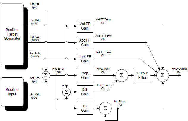
Algorithm
Each closed loop motion command issued to the RMC specifies a target profile, which defines where the axis should be at any given moment. For each loop time when the axis is in closed loop control, the RMC uses the specified target profile to calculate the desired position of the axis at that moment (called the Target Position) and subtracts the Actual Position to determine the Position Error. The Position PID algorithm then uses this information, together with the gains and feed forwards, to calculate how much Control Output should be generated to move the axis to the Target Position. The values of the gains and feed forwards must be set to achieve proper control. The process of setting the gains is called tuning and is done as part of the setup procedure.
The Position PID uses the gains and feed forwards listed below. Each gain or feed forward is multiplied by some quantity related to the Target Position and Actual Position to come up with a percentage. The resulting percentages are all summed and then multiplied by the maximum output (typically 10V), to come up with the Control Output voltage for that loop time.
Proportional Gain
The Proportional Gain is multiplied by the Position Error. This is the most important gain.
Integral Gain
The Integral Gain is multiplied by the accumulated Position Error. This helps the axis get into position over time.
Differential Gain
The Differential Gain is multiplied by the difference between the Target and Actual Velocities. This helps the axis keep up with quick changes in velocity.
Velocity Feed Forward
The Velocity Feed Forward is multiplied by the Target Velocity.
Acceleration Feed Forward
The Acceleration Feed Forward is multiplied by the Target Acceleration.
Jerk Feed Forward
The Jerk Feed Forward is multiplied by the Target Jerk. The Jerk Feed Forward is not necessary for most applications.
In addition, higher-order gains may be used if Acceleration Control or Active Damping are selected.
Tuning Position PID
See the Tuning Overview topic for details. The Tuning Wizard can be used to tune position PID control.
Diagram
See Also
Copyright © 2026 Delta Computer Systems, Inc. dba Delta Motion