The following manual tuning procedure may be used to tune many position axes, hydraulic axes and motors in velocity mode. This procedure works for Position PID control. Please read the Tuning Overview topic before following this procedure. There is no substitute for experience when tuning an axis. This procedure offers some guidelines, tips, and suggestions for tuning your system. While these steps will work for some systems, they may not be the best for a particular system.
Before beginning the tuning procedure, set all the gains and feed forwards on the axis to zero.
Tuning Procedure
Before beginning the tuning procedure, make sure you have completed the steps in the StartUp Procedure up to the Tuning section. You must be able to move your actuator properly (a positive Control Output causes increasing position) and have valid feedback.
Pre-Tuning Steps:
These steps come before actually tuning the gains.
This step is for verifying that the system wiring and setup is correct before doing any closed loop control.
In the Command Tool, issue a Direct Output (9) command to the axis. Use small Output value, such as 0.050-0.150 V. Use a Ramp Rate of 100. If the axis does not move, increase the Output until the axis begins to move.
DANGER: The Direct Output (9) command disables the safety features on the RMC! Use this command carefully!
A positive Control Output should yield increasing position units. If it does not, do the following:
On the RMCTools toolbar, click the Axis Tools button ![]() .
.
In the Axis Parameters Pane, on the Setup tab, toggle the Invert Output Polarity parameter, then click the Download button ![]() .
.
Issue a Direct Output (9) command again with a negative drive. This should yield decreasing position units.
If the axis exhibits a deadband, you may need to use the Deadband parameters.
Check Whether the System Exhibits a Deadband:
Give increasing amounts of Output to the axis with the Direct Output (9) command until the system starts to move.
The value of Output at which the system starts to move is your deadband. If this value is approximately 0.4 V or greater, or if the axis begins to move quickly at the deadband value, you should probably use the deadband parameters. If the point at which it begins to move it is less than 0.4 V, it is left to the discretion of the designer.
Set the Deadband Parameters:
If you found that your system has a deadband, set the deadband parameters in the following manner:
On the RMCTools toolbar, click the Axis Tools button ![]() .
.
In the Axis Parameters Pane, on the All tab, expand the Output section.
Set the Output Deadband parameter to the value of your deadband.
Set the Deadband Tolerance to a small value.
Click the Download button ![]() to apply the changes to the RMC.
to apply the changes to the RMC.
If you are using a non-linear hydraulic valve, set the valve linearization parameters as described in the Valve Linearization topic. Delta does not recommend using a non-linear valve if a linear valve is available.
Some systems may drift significantly when the Control Output is at zero volts, which may adversely affect control. Use the Output Bias parameter to adjust the output such that the axis does not move when you issue an Open Loop command with zero volts Control Output. The RMC always adds the Output Bias to the Control Output.
Check if your system need Output Bias:
Issue an Open Loop Rate (10) command to the axis. Use an Output of zero and a Ramp Rate of 100.
If the axis moves significantly, you need to set the Output Bias.
Set the Output Bias:
In the Axis Tools, in the Axis Parameters Pane, on the Tune tab, enter a small number in the Output Bias parameter, such as 0.05 V or -0.05 V.
Keep increasing (or decreasing) the number until the axis stands still.
Click the Download button ![]() to apply the changes to the RMC.
to apply the changes to the RMC.
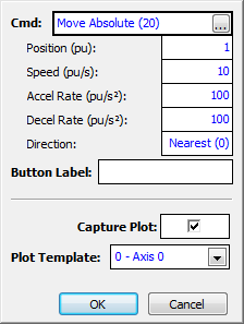
In the Tuning Tools, set up the command buttons so that one button will move the axis one direction, and the other will move it in the other direction.
Click the down arrow on the command button ![]() .
.
Enter the Position, Speed, Acceleration, Deceleration, and Direction (Nearest for linear axes) for the Move Absolute command, then click OK.
Tip:
For a typical hydraulic cylinder, the Accel and Decel parameters of the Move absolute command are typically on the order of 10 to 100pu/sec2. The speed is typically between 1 and 30pu/sec.
Example:
Repeat the previous step for the other command button. Enter the same velocity, acceleration, and deceleration, but a different position.
If your system behaves differently in each direction of motion, you will need to set the Symmetrical/Ratioed parameter is set to Ratioed. This will provide two Velocity Feed Forwards, one in each direction of motion. The other gains will be ratioed according to the Velocity Feed Forwards, resulting in the same control in both directions.
If you have a single-rod hydraulic cylinder, choose Ratioed.
The Symmetrical/Ratioed parameter can be accessed in the Tuning Tools on the Tune tab in the Axis Parameters section. Remember to download the changes by clicking the Download ![]() button.
button.
Tuning Steps:
These steps are for adjusting the tuning gains. Use the Tuning Tools for these steps.
6. ![]() Adjust the Proportional Gain
Adjust the Proportional Gain
The Proportional Gain must be adjusted to gain some control over the system for continuing the tuning procedure. You will fine-tune it later.
Start with a small value of Proportional Gain. Remember that it is a floating point number, and you may have to start with a number smaller than 1, depending on your system. When you change the gain, click the Download button ![]() to apply the change to the RMC.
to apply the change to the RMC.
From the Command Tool, issue the Move Absolute (20) command to move the axis.
Tip:
For a typical hydraulic cylinder, the Accel and Decel parameters of the Move absolute command should be on the order of 20 -100. The speed is typically between 1 and 30.
Slowly increase the Proportional Gain as you make moves. Increase it until the following are true:
The Actual Position gets to the Command Position reasonably quickly.
During the constant speed portion of the move, the Actual Position parallels the Target Position.
If the system begins to oscillate, decrease the gain. In this step, do not expect the Actual Position to track the Target Position very well during the move.
Once you gain control over the system, increase the speeds and accelerations of your commands to values that will be used during normal machine operation.
Plots
Look at these plots for examples of good and bad plots at this step. Be aware that not all systems will be like these examples.
The Actual Position lags the Target Position and takes a long time to get to the Command Position.
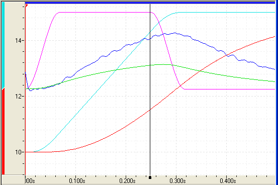
The axis has started to oscillate, which is evident from the Actual Speed and Control Output.
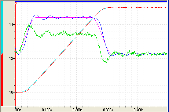
The Actual Position parallels the Target Position during the constant velocity portion of the move and does not overshoot.
7. ![]() Adjust the Velocity Feed Forward
Adjust the Velocity Feed Forward
In many systems the Velocity Feed Forward parameter is the most important parameter for position tracking during a move. To adjust the Velocity Feed Forward:
Start with a small value of Velocity Feed Forward. Remember that it is a floating point number, and you may have to start with a number smaller than 1, depending on your system.
Tip:
Use the Adjust VFF button in the Tuning Tools to automatically determine the Velocity Feed Forward. Make a move, wait for it to complete, then click Adjust VFF. Repeat for the other direction.
Make long slow moves in both directions. Adjust the Velocity Feed Forward until the axis tracks within 10% in both directions.
If you are using Ratioed gains, make sure to adjust both Velocity Feed Forwards.
Click the Download button ![]() to apply the changes to the RMC.
to apply the changes to the RMC.
If the Symmetrical/Ratioed parameter is set to Ratioed, you will have two Velocity Feed Forwards, one for each direction of motion. Make sure to tune both.
Plots
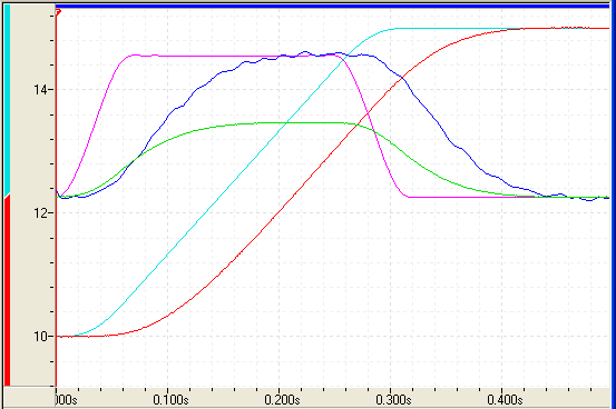
Look at these plots for examples of good and bad plots at this step. Be aware that not all systems will be like these examples.
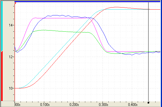
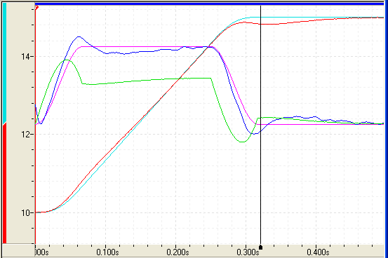
![]() Too little Velocity Feed Forward
Too little Velocity Feed Forward
The Actual Position lags the Target Position during the entire move.
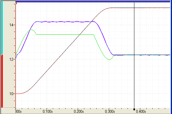
![]() Too much Velocity Feed Forward
Too much Velocity Feed Forward
The Actual Position starts leading the Target Position.
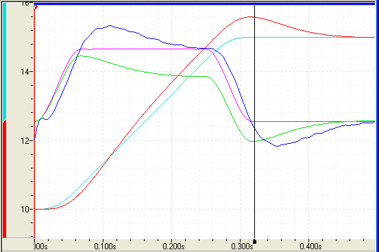
The Actual Position tracks the Target Position perfectly during the latter half of the move.
8. ![]() Adjust the Acceleration Feed Forward
Adjust the Acceleration Feed Forward
The Acceleration Feed Forward parameter is particularly useful for systems moving large masses with relatively small cylinders. Such systems often have a delay before the start of movement. The Acceleration Feed Forward terms can help compensate for this delay.
Start with a small value of Acceleration Feed Forward. Remember that it is a floating point number, and you will very likely have to start with a number much smaller than 1, such as 0.001, depending on your system.
Tip:
For a 2.5 in bore hydraulic cylinder with a max velocity of 30 in/sec, the Acceleration Feed Forward is typically on the order of 0.01 to 0.3. Start with a small value.
Look for following errors during acceleration and deceleration. Increase the Acceleration Feed Forward parameter until the errors disappear.
If you are using Ratioed gains, make sure to adjust both Acceleration Feed Forwards.
Click the Download button ![]() to apply the changes to the RMC.
to apply the changes to the RMC.
Plots
Look at these plots for examples of good and bad plots at this step. Be aware that not all systems will be like these examples.
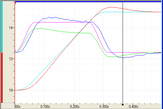
![]() Too little Acceleration Feed Forward
Too little Acceleration Feed Forward
The Actual Position lags the Target Position during the acceleration at the beginning of the move, and overshoots during the deceleration at the end of the move.
![]() Too much Acceleration Feed Forward
Too much Acceleration Feed Forward
The Actual Position starts leading during the acceleration and undershoots during the deceleration.
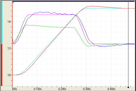
![]() Correct Acceleration Feed Forward
Correct Acceleration Feed Forward
The Actual Position tracks the Target Position well during the acceleration and deceleration.
9. ![]() Readjust the Proportional Gain
Readjust the Proportional Gain
Proportional Gain affects the responsiveness of the system. Low gains make the system sluggish and unresponsive. Gains that are too high make the axis oscillate or vibrate.
Slowly increase the gain. When you see a tendency to oscillate as the axis moves or stops, reduce the gain by 10 to 30 percent.
Tip:
For a 2.5 in bore hydraulic cylinder with a max velocity of 30 in/sec, the Proportional Gain is typically on the order of 20 to 300. Start with a small value.
Click the Download button ![]() to apply the changes to the RMC.
to apply the changes to the RMC.
Many hydraulic systems do not require a large Integral Gain. However, it is usually desirable to have some Integral Gain to help compensate for valve null drift or changes in system dynamics. Some systems may require larger Integral Gain, in particular if they are moving a large mass or are nonlinear. Too much Integral Gain will cause oscillations and overshoot. The Integral Gain is helpful for getting into position and for tracking during long, slow moves. It will not significantly affect tracking during short, fast moves.
Tip:
Typically, the Integral Gain should be 3 to 5 times greater than the Proportional Gain.
Click the Download button ![]() to apply the changes to the RMC.
to apply the changes to the RMC.
Too little Integral Gain:
The system may not get into position very quickly, and it will take a long time to recover from quick changes in the system, for example static friction, load changes, or obstacles.
Too much Integral Gain:
The system will begin oscillating.
Correct Integral Gain:
The system will get into position quickly, and any system changes will be quickly corrected.
11. ![]() Adjust the Differential Gain
Adjust the Differential Gain
Differential Gain may greatly enhance performance on many hydraulic systems. It is used mainly on systems that have a tendency to oscillate. This happens when heavy loads are moved with relatively small cylinders. Differential Gain will tend to dampen out oscillations and help the axis track during acceleration and deceleration. This will positively affect short, fast moves.
A disadvantage of Differential Gain is that it amplifies position measurement noise. If there is too much noise or the gain is too high, this can cause the system to chatter or oscillate. However, this can be compensated for by using the Output Filter. Systems that are difficult to tune can sometimes be drastically improved by using the Output Filter together with the Differential gain.
Many systems do not require any Differential Gain.
Start with a small value of Differential Gain. Remember that it is a floating point number, and you will may have to start with a number much smaller than 1, depending on your system.
Tip:
For a 2.5 in bore hydraulic cylinder with a max velocity of 30 in/sec, the Differential Gain, if any, is typically on the order of 0.01 to 2. Start with a small value.
Increase the Differential Gain. It may help the system track better. If it starts oscillating or chattering, decrease the gain.
If the drive output during the constant velocity portion of the move is smooth, the Differential Gain is perhaps not set high enough.
When the Differential Gain is properly adjusted, the drive output may look "fuzzy." This indicates that the drive is responding to the minute errors of the axis. Not all systems allow the differential gain to be set high enough for the drive to be "fuzzy".
Note:
If you use Differential Gain, you may be able to increase the Proportional Gain somewhat without making the system oscillate.
If the system starts chattering or oscillating before it can achieve proper control, try using the Output Filter.
Click the Download button ![]() to apply the changes to the RMC.
to apply the changes to the RMC.
Too little Differential Gain:
The system will not keep up during acceleration and deceleration.
Too much Differential Gain:
The system will exhibit rapid oscillation.
Correct Differential Gain:
The system will track properly during acceleration and deceleration.
If the axis is not tracking very well at this point, the Output Filter may help. It can significantly improve control of difficult systems. Without the Output Filter, the Differential Gain can cause the Control Output to oscillate, causing oscillation of the axis. By using the output filter, the Differential Gain can be increased significantly to help the Actual Velocity track the Target Velocity.
Typically, the Output Filter can be set to a value close to the natural frequency of the system. For example, if a system tends to oscillate at 10 Hz, a good starting value for the Output Filter is 10 or higher. After setting the Output Filter, you may be able to increase the Differential and Proportional Gains to improve control. If it does not help, try smaller and higher values of Output Filter, then try increasing the Differential and Proportional Gains again.
Keep in mind that the Output Filter does not always help.
If you have not yet done so, increase the Speed and Acceleration values of the moves. Look for following errors, overshoot, or oscillations.
If an Output Saturated error occurs, there is not enough drive capacity to drive the axis at the requested Speed or Acceleration. Should this occur, reduce the Speed and/or Acceleration and Deceleration.
If a Following Error occurs during acceleration and deceleration and adjusting the Gains and Acceleration Feed Forward does not help, the Acceleration and Deceleration ramps are too steep for the response of the system.
If the actual position lags or leads the target position during the entire constant velocity section of the move, adjust the Feed Forwards.
Should the system seem a little sloppy, try increasing the Proportional Gain.
If the Control Output never gets very high, the gains can probably be increased for better control. If the Control Output is too high, or an overdrive error occurs, the system is not capable of performing the requested move. The Speed, and/or Accelerations may need to be decreased.
If the system vibrates while in position, the gains may be too high, or the Dead Band value may need to be increased. However, if the oscillation is not caused by a deadband in the system, adjusting the Dead Band value will not help! A rule of thumb is to set the Dead Band Eliminator value to half of the peak-to-peak oscillation of the drive output while in position.
The final tuning of the system should be made at the speed of intended operation.
14. ![]() Save your Settings to Flash
Save your Settings to Flash
To retain your settings in the RMC in the event of a power loss, you must save the settings to Flash:
On the Controller menu, click Update Flash.
See Also
Copyright © 2026 Delta Computer Systems, Inc. dba Delta Motion