|
Type: |
|
|
Address: |
RMC75: %MDn.41, where n = 12 + the axis number RMC150: %MDn.41, where n = 24 + the axis number RMC200: %MDn.151, where n = 24 + the axis number |
|
System Tag: |
|
|
How to Find: |
Axes Parameters Pane, All tab: Output |
|
Data Type: |
|
|
Units: |
pu |
|
Range: |
≥ 0 |
|
Default Value: |
0 |
Description
In closed-loop position control (Position PID or Position I-PD), the Deadband Tolerance parameter works together with the Output Deadband to reduce "hunting" and ratio the deadband for smoother motion. The Deadband Tolerance has no effect on control in open-loop or velocity (Velocity PID or Velocity I-PD) control.
The Deadband Tolerance affects two areas:
Anti-Hunting
When the target is stopped, and the Position Error is less than the Deadband Tolerance or less than the position corresponding to one half of a transducer Raw Count, then the Integral Output Term will only be allowed to wind down. In systems with a deadband, this avoids ratcheting the axis back and forth around the deadband. Notice that this works even if the Output Deadband is 0. If the Deadband Tolerance is zero, this still works with the window defined by the position corresponding to one half of a transducer Raw Count.
Deadband Ratioing
The Deadband Tolerance specifies a Position Error window inside of which only a fraction of the Output Deadband is applied. This minimizes chattering, which might otherwise be caused by the Output Deadband. If the Position Error is greater than the Deadband Tolerance, the Output Deadband is applied normally.
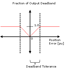
Deadband Ratioing works as shown in the graph below:
If the Deadband Output is non-zero, the target velocity is zero, and the absolute value of the Position Error is less than the Deadband Tolerance, only a fraction of the Output Deadband, proportional to the Position Error, is applied, as shown in the graph below.
If the absolute value of the Position Error is greater than the Deadband Tolerance, the full Output Deadband is applied, as shown in the graph below.
Figure 1: Deadband Tolerance
Control Modes
The Deadband compensation applies to all the closed-loop control modes: Position PID, Position I-PD, Velocity PID, Velocity I-PD.
Pressure/Force Limit on Position-Pressure or Position-Force Axes
The Output Deadband is applied as normal, based on position. The Deadband Tolerance controls the integrator for the position component. If the target is stopped and the position error is less than the window then the position of the integrator is only allowed to wind down. When the axis is pressure/force limited then the position integrator is not used and the Deadband Tolerance has no effect.
Pressure-Only or Force-Only Axes
The Output Deadband applies to pressure/force control. If the Deadband Tolerance value is non-zero, then the Output Deadband will not apply if the Target Pressure or Target Force is zero. Otherwise, the value of the Deadband Tolerance has no meaning.
Velocity Control
The Output Deadband applies to velocity control. If the Deadband Tolerance value is non-zero, then the Output Deadband will not apply if the Target Velocity is zero. Otherwise, the value of the Deadband Tolerance has no meaning.
See Also
Parameter Registers | Output Deadband
Copyright © 2026 Delta Computer Systems, Inc. dba Delta Motion