Open topic with navigation
Using
Allen-Bradley Controllers via Message Block
Most Allen-Bradley PLCs and PC-based controllers
(ControlLogix, CompactLogix, SLC5/05, PLC-5, SoftLogix, etc.) support
serial RS-232 and Ethernet communications, either built-in or through
an add-on module.
This topic describes how to communicate with
the RMC from the Allen-Bradley PLCs via the Message (MSG) block. For information
on using EtherNet/IP I/O with the Logix PLCs, see the Using
Allen-Bradley Controllers via EtherNet/IP topic. For details on using
Allen-Bradley's RSView operator interface with the RMC, see the RSView
with the RMC topic.
The Allen-Bradley PLCs can read or write from
registers in compatible remote devices such as other Allen-Bradley PLCs
or the RMC. The RMC contains floating point (F) files, all of which are
accessible over serial or Ethernet from the Allen-Bradley PLCs. See DF1 Addressing
for details on finding those registers and their addresses.
If you need help setting up your Ethernet
network, either consult your network administrator, or for simple stand-alone
networks, see Setting
Up a Standalone TCP/IP Network.
For setting up the RMC75S serial settings,
see the Configuring
Serial Communications topic. For setting up the RMC75E,RMC150E, or
RMC200 Ethernet, see the RMC
Ethernet Setup topic.
Example Programs
Delta provides example PLC programs to help
you quickly set up the communications between your PLC and the RMC. See
the downloads
section of Delta's website at https://deltamotion.com.
Message (MSG) Block
The Allen Bradley PLCs and controllers listed
above all use the same ladder logic block to communicate over Ethernet:
the Message (MSG) block. This block takes a number of parameters, which
are briefly described below. For a complete description of the parameters,
refer to Allen-Bradley's Instruction Set Reference Manual for the appropriate
PLC.
MSG Parameters
The MSG block parameters differ slightly depending
on the controller and programming software. The parameters used by RSLogix
5 version 3.2.0.0, RSLogix 500 version 6.30.00, and RSLogix 5000 version
17.00.00 for the PLC-5, SLC 5/05, ControlLogix and CompactLogix controllers
respectively are described below. The SoftLogix 5 parameters are similar.
 ControlLogix and CompactLogix MSG Block
Parameters
ControlLogix and CompactLogix MSG Block
Parameters
The ControlLogix or CompactLogix MSG block is displayed as follows. More detailed information on the MSG block is available in Allen Bradley publication 1756-RM003L-EN-P, Logix5000 Controllers General Instructions.
The Message Control portion of the MSG requires a tag.
To create a tag:
-
Right-click the "?" and choose NewTag.
-
Type a name in the Name field.
-
Make sure the Data Type is MESSAGE.
-
Click Configure. The Message Configuration dialog will open.
-
2, station address
where station address is the node address of the RMC. For example, if the node address is 3, the path is:
2, 3
Note:
The "2" is the port number for the serial port on the ControlLogix CPU.
SLC 5/05 MSG Block Parameters
The SLC 5/05 MSG block is displayed as the following:
|
Parameter
|
Description
|
|
Type
|
This
parameter is always set to Peer-To-Peer for serial or Ethernet
communication channels.
|
|
Read/Write
|
This
parameter should be set to Read
to read registers from the RMC and to Write
to write registers to the RMC.
|
|
Target Device
|
This
should be set to 500CPU
for communicating with the RMC.
|
|
Local/Remote
|
This
parameter has possible values of Local and Remote. It should
be set to Local for
communicating with the RMC.
|
|
Control Block
|
This parameter points to a block
of integer-file registers (51 registers for Ethernet, 12 for
serial). Set this to a block of registers, and then
use the Setup Screen option in the MSG ladder logic block
to modify those register values:
MultiHop: This parameter
should be set to No.
-
Local/Remote and Bridge Parameters:
In most applications these will be set to Local and there
will be no bridge parameters. If you are using a bridge then
these parameters will need to be used. However, this is beyond
the scope of RMC documentation. Refer to your Allen-Bradley
documentation for instructions on using these fields.
|
|
|
|
Note:
For the SLC505, if the start of communications with the RMC exhibits several minutes of delay after power-up, it is because your SLC processor and/or firmware is old. Newer SLC processors do not have this problem.
PLC-5 MSG Block Parameters
The PLC-5 MSG block is displayed as follows:
The Control parameter points to a block of 51 N-file (integer) registers or two (2) MG-file (message) registers. Set this to an unused block of registers, and then use the Setup Screen option in the MSG ladder logic block to modify those register values:
|
Register
|
Description
|
|
This PLC-5
|
This section holds parameters
for the PLC-5:
-
Communication Command:
From this drop-down list, select PLC-5 Typed Read to read
values from the RMC, or PLC-5 Typed Write to write values
to the RMC.
-
Data Table Address:
Enter the address of the first Allen-Bradley PLC register
to read RMC registers into, or to write to RMC registers
from.
-
Size in Elements: Enter
the number of RMC registers to read or write in this field.
Transfers are limited to 1000 bytes for PLC-5 Typed Reads
and Writes. Therefore, this limit is 500 integers, 250
floats, etc.
-
Port Number: Set this
to the Ethernet channel number. For the PLC-5, this should
be channel #2.
|
|
Target Device
|
This section holds parameters
for the target device:
MultiHop: This parameter
should be set to No.
Ethernet (IP) address: Set
this to the IP address of the RMC you wish to communicate
with.
Local Node Addr (dec): Enter
the node address of this RMC. The node address of the RMC
is set up in the Serial
Port Settings Page. The node address entered on that screen
is in decimal, so it is recommended that you enter the same
number in the dec field.
|
MicroLogix
MSG Parameters
The MicroLogix MSG block is displayed as follows:
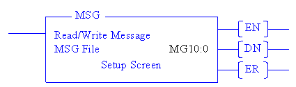
Serial Communications:
To edit the parameters of the message block, select the MSG block, enter an unused MSG file in the MSG File parameter, and double-click Setup Screen. This brings up a dialog with the following options:
This Controller: This section holds parameters for the MicroLogix.
Communication Command: From this drop-down list, select PLC-5 Typed Read to read values from the RMC, or PLC-5 Typed Write to write values to the RMC. The SLC Typed Read or Write will also work, but is limited to 58 registers.
Data Table Address: Enter the address of the first Allen-Bradley PLC register to read RMC registers into, or to write to RMC registers from.
Size in Elements: Enter the number of RMC registers to read or write in this field. The MicroLogix can transfer 1 to 41 integers.
Channel: Set this to the channel number of the serial port you want to use. The MicroLogix 1500 LRP Series B can use either channel 0 or 1, but all other MicroLogix PLCs will always use channel 0.
Target Device: This section holds parameters for the target device.
Message Timeout: Indicate the number of seconds to wait for the RMC to respond before determining that the attempt failed. This can be set as low as a few seconds.
Data Table Address: Enter the address of the first RMC register to read or write in this field. See the Registers Maps topic for help on addresses.
Local Node Addr (dec): Enter the node address of this RMC. The node address of the RMC is set up in the Serial Port Settings Page. The node address entered on that screen is in decimal, so it is recommended that you enter the same number in the dec field.
Local/Remote and Bridge Parameters: In most applications these will be set to Local and there will be no bridge parameters. If you are using a bridge then these parameters will need to be used. However, this is beyond the scope of RMC documentation. Refer to your Allen-Bradley documentation for instructions on using these fields.
Ethernet Communications (MicroLogix 1100):
-
In the RSLogix project tree, in the Data Files, create a message File (MG) data file and a Routing Information (RI) data file.
-
Add the MSG block to the ladder logic. Select the MSG block, enter the an address in the Message data file you just created (e.g MG9:0), and double-click Setup Screen.
This brings up a dialog with a General tab with the following options:
This Controller: This section holds parameters for the MicroLogix.
Channel: To use Ethernet on the MicroLogix 1100, choose 1 (integral).
Communication Command: This parameter can be set to PLC5 Read, PLC5 Write, 500CPU Read, or 500CPU Write. The type of PLC selected is not important, but the Read or Write determines whether you will read registers from the RMC or write registers into the RMC.
Data Table Address: Enter the address of the first Allen-Bradley PLC register to read RMC registers into, or to write to RMC registers from.
Size in Elements: Enter the number of RMC registers to read or write in this field.
Target Device: This section holds parameters for the target device.
Message Timeout: Indicate the number of seconds to wait for the RMC to respond before determining that the attempt failed. This can be set as low as a few seconds.
Data Table Address: Enter the address of the first RMC register to read or write in this field. See the Registers Maps topic for help on addresses.
Local / Remote: Choose Local.
Routing Information File (RI): Enter the address in the Routing Information File that you intend to use (e.g. RI10:0).
-
On the Multi-hop tab, in the To Address box, enter the IP address of the target RMC. For example, 192.168.0.219.
Using the MSG Block in Ladder Logic
The Allen-Bradley MSG block may take multiple
ladder scans to complete. Therefore, it is important to enable the MSG
block for the correct amount of time. Specifically, the MSG block must
be energized until the message control's enable (EN) bit turns on. Following
the ladder samples to ensure proper functionality:
Read or Write Continuously
Using the Examine
If Open instruction as shown below fulfills two requirements of continuous
MSG transactions. First, it will keep the block energized until the EN
turns on, and second, it de-energizes the MSG block once the transactions
is started so that when the transaction is completed (EN goes low again),
the MSG block sees a rising edge on its input, thus repeating the transaction:
Read or Write Once
This sample takes
care to keep the MSG block energized until the MSG block starts, as indicated
by the enable (EN) bit turning on. Once this happens, the application-controlled
TriggerOnce coil is turned off. The message control's Done (DN) or Error
(ER) bits can be used to process the results of the transaction.
Reading DWORDs from the RMC
All items in the RMC have F-file addresses.
Allen-Bradley defines F file data as 32-floating point values. All the
RMC registers have F-file addresses, even if they are DWORDs or DINTs.
For example, the Status Bits and Error Bits in the RMC are DWORDS. To
read these values, read them using their F addresses as given in the RMC.
Then, in the PLC, use the COP instruction (RSLogix5000), or CPW instruction
(RSlogix500) to copy the data to a register or tag of the correct data
type, for example, an N register, L register, or DINT tag. The COP instruction
preserves all the bits correctly, and the resulting values will be correct.
If the PLC must write a DINT or DWORD in the
RMC, use a similar method.
See Also
Ethernet Overview
| RMC75
Register Map | RMC150
Register Map | RSView with the RMC
Send comments on this topic.
Copyright © 2026 Delta Computer Systems, Inc. dba Delta Motion