
Creating a new EtherCAT network involves the following main steps, which are described in this topic:
Physically connect EtherCAT devices
Create the EtherCAT network in RMCTools
Configure the SubDevices
After these steps, data may be assigned to axes as described in Assigning EtherCAT Data to Axes.
If the network must be modified after the initial creation and configuration, refer to Editing the EtherCAT Topology.
Related content:
For a general explanation of EtherCAT topologies, see EtherCAT Network Topologies.
For instructions on adding, removing or re-ordering SubDevices in an existing EtherCAT network, after the network has initially been created and configured, see Editing the EtherCAT Topology.
Physically Connect the SubDevices
SubDevices can be connected with Ethernet cables in various ways to create a network, as described in EtherCAT Network Topologies.
Important! Do not use Ethernet switches! EtherCAT is not compatible with normal Ethernet (although EtherCAT does use Ethernet cables). Ethernet switches cannot be used with EtherCAT. Specialized EtherCAT junctions may be used instead, as described in EtherCAT Network Topologies. EtherCAT junctions are often not necessary, since devices can be connected in a line topology.
Cables and Connectors
EtherCAT requires Ethernet cable that meets the requirements of at least CAT 5. EtherCAT cables use 4 wires.
The cable length between two EtherCAT devices must not exceed 100 m (special Extended Distance components may allow up to 300 m).
The most commonly used connectors are RJ45, M12 (4 pole, D-coded), and M8 (4 pole, A-coded). Cable connectors are male, and device connectors are female. The RMC ECAT module has RJ45 jacks.
Molded cable assemblies are commonly available. Typical cables assemblies needed in a network are: RJ45-RJ45 , RJ45-M12 , RJ45-M8 , M12-M12 , M8-M8
Field-wirable connectors are also readily available, which may be necessary for M8 to M12 connections, as M8 to M12 cable assemblies are not as readily available.
SubDevices Connection Order
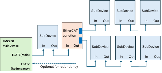
It is important to connect the IN and OUT ports of the SubDevices correctly. Port labeling varies - instead of IN and OUT, you may see Port 0 and Port 1, or Port 1 and Port 2, or A and B.
The network connections must always follow this order:
The RMC’s ECAT1 port (MainDevice) connects to the IN port of the first SubDevice.
The OUT port of that SubDevice connects to the IN port of the next SubDevice.
The OUT port of the last SubDevice need not be connected. If redundancy is required, connect the OUT port of the last SubDevice to the ECAT2 (redundancy) port on the RMC.
A simple network may look like this:
A more complicated network may include EtherCAT junctions. Use of junctions may limit redundancy.
Create the Network in RMCTools
After physically connecting the network SubDevices to the RMC as described above, do the following:
Make sure that the ESI files for the new SubDevices are installed. See EtherCAT SubDevice Information (ESI) File for details.
In RMCTools, use Configure Using Network Scan to automatically detect the network and create it in RMCTools:
Make sure RMCTools is online with the RMC and open the EtherCAT Editor.
In the EtherCAT Editor, on the toolbar, click  Configure Using Network Scan.
Or, on the EtherCAT menu, select Configure Using Network Scan.
A caution appears warning that this will reset all the configuration settings. Click Yes to continue.
All the SubDevices on the network should now appear in the EtherCAT Explorer.
If the SubDevices do not appear correctly, make sure the ESI files are loaded.
Tip: This method will have default settings in the SubDevices. For large systems with many identical SubDevices, you may wish to create SubDevices with pre-defined configuration settings. See Adding SubDevices with Configuration below.
Configure the SubDevices
After creating the network in RMCTools as described above, the SubDevices listed in the EtherCAT Editor must be configured. In the EtherCAT Editor, clicking a SubDevice shows the configuration tabs. The number of tabs varies by SubDevice and the configuration required depends on how the SubDevice will be used.
The required configuration varies widely among SubDevices. For instructions on configuring specific types of devices, see:
The possible configuration tabs and settings that may need to be configured are:
General tab
Set the Station Address and Name
Modules tab
If available, choose modules as described in EtherCAT Modules. Modules usually pre-define the PDO Mapping and Init Commands.
PDO Mapping tab
Select the data (Process Data Objects) to be communicated between the MainDevice and the SubDevice. See EtherCAT Process Data Object (PDO).
Process Data tab
This tab allows the PDO data to be assigned to RMC addresses (in the EtherCAT Input/Output Data Maps), with optional tag names, so the data is accessible by user programs, plots, or external devices that communicate with the RMC.
See EtherCAT Input/Output Data Maps for details.
Notice that EtherCAT data that will be assigned to axis feedback or output does not need to be added to the EtherCAT Input/Output Data Maps.
Ethernet tab
This is only necessary in some situations when using Ethernet over EtherCAT (EoE).
Advanced Options tab
The identification checking may be useful to prevent mixing up the order of identical devices on the network. The other settings on this tab typically do not need to be configured.
Distributed Clocks tab
If the SubDevice supports Distributed Clocks, set the Operation Mode to enable it. See Distributed Clock Synchronization for details.
Init Commands tab
Init commands are necessary for some devices, typically for setting certain modes. See EtherCAT Init Commands for details.
CoE Object Dictonary tab
This tab is not for configuration. Rather, it lists the accessible objects in the device, which may possibly be used in the PDO Mapping, Init commands, or in SDO communication.
Adding SubDevices with Configuration
For large systems with many identical SubDevices, you can reduce setup time by creating SubDevices with pre-defined configuration settings.
The two main methods are:
Copying a configured SubDevice and pasting it.
Exporting a SubDevice Configuration Interface (SCI) file to be used later, or on a different PC.
With these methods, you will not use Configure Using Network Scan. Instead, you will work directly in the EtherCAT Explorer to manually create the network. To create the network, you will want to know the physical layout of the network so you can recreate that in the EtherCAT Explorer. To view the physical layout of the network You can use the Network Mismatch Analyzer, or the Scan function in the the Edit Topology dialog. If you use the Edit Topology dialog, do NOT apply changes, or it will overwrite all your network settings!
Copying and Pasting SubDevices
Copying and pasting a SubDevice will keep most of the SubDevice settings. It will not keep the Data Map Address settings on the Process Data tab. The Station Address and Ethernet settings may automatically be changed to prevent conflicts.
To copy and paste SubDevice(s):
In the EtherCAT Editor, right-click a SubDevice and select Copy SubDevice(s).
Determine where you wish to add a SubDevice. Right-click the device above that location and select Paste SubDevice(s) After.
You can also paste into a different controller in the same instance of RMCTools, or into another instance of RMCTools.
Review the SubDevice settings in the tabs to make sure they are correct for your system. Pay special attention to the Station Address, the Process Data tab and the Ethernet tab, as that information may have changed.
Using a SubDevice Configuration Interface (SCI) file
A SubDevice Configuration Interface (SCI) file describes a specific complete configuration for an EtherCAT SubDevice. SCI files can be created in RMCTools and will include the PDO configuration, Init Commands and DC options. SCI files can be used to add identical SubDevices to the network, which is useful for large systems with many identical SubDevices.
An SCI file provides only the specific configuration of a SubDevice. It does not provide the option to further change all the configuration settings. For example, for SubDevices that support Modules, the SCI file will include the selected module, but a SubDevice added based on the SCI file will not provide the option of editing the modules. An SCI file cannot be created from a SubDevice that was added from an SCI file.
An SCI file will not keep the Data Map Address settings on the Process Data tab. The Station Address and Ethernet settings may automatically be changed to prevent conflicts.
To export a SubDevice(s) to an SCI file:
In the EtherCAT Editor, right-click a SubDevice and select Export SCI.
Choose a location and filename, then click Save. You will use the filename later to find the SCI file in the EtherCAT ESI Manager.
To add a SubDevice from an SCI file:
On the Tools menu, select EtherCAT ESI Manager.
Click Add File, browse to the SCI file, select it, and click Open.
Close the EtherCAT ESI Manager.
In the EtherCAT Editor, determine where you wish to add the SubDevice. Right-click the device above that location and select Add SubDevice(s) After. The Append EtherCAT SubDevice dialog opens.
Check the Show Hidden SubDevices box.
In the SubDevices list, locate the SCI item you added, select it, and click OK.
It will be listed under the Manufacturer’s name. The second column will display the name of the file you chose when you exported to an SCI file.
Review the SubDevice settings in the tabs to make sure they are correct for your system. If you need to change settings, you may need to add the SubDevice from the ESI file, since the SCI file does not offer full configurability.
See Also
EtherCAT Overview | Assigning EtherCAT Data | EtherCAT Editor
Copyright © 2026 Delta Computer Systems, Inc. dba Delta Motion