Cascade control is supported with any number of loops up to the number of axes supported by the RMC.
What is Cascade Control?
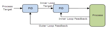
Cascade control is a control algorithm in which the output of one control loop provides the target for another loop, as shown in the diagram below.
The ultimate goal of the cascaded loops is to control the end process. Cascade control can provide precise control for certain difficult systems, for example systems in which some lag time exists.
To better understand cascade control, consider the following example in hydraulic motion control:
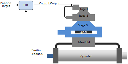
The figure above shows a very large hydraulic cylinder with a 3-stage proportional valve. The goal is to control the cylinder position.
The first two valve stages have internal electronic controls, and all we need to know about them is that the first two stages will produce a velocity on the third stage that is roughly proportional to the Control Output signal received by the valve. The third stage has no electronic controls.
A standard PID control loop can be applied to this system, as shown in the figure. However, this results in poor control. The valve spool responds very quickly compared to the cylinder. Therefore, when the Position Target of the system (the desired position of the cylinder) changes, the valve spool will immediately move over its full length of travel, while the cylinder has barely begun moving, and when the actual position eventually catches up to the target, the spool will immediately move back the full length, and in that way, the system can begin to oscillate and will result in poor control.
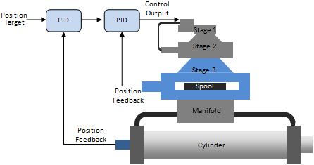
A better method is to apply an additional inner PID loop to the valve in a cascaded configuration, as shown in the figure below. This requires spool position feedback from the third stage of the valve. The valve will then provide a much more linear flow in relation to the Control Output, which will make the outer position PID much easier to tune and will provide better control.
Cascade Control Advantages
Allows inner loop to handle non-linear valve and other final control element problems.
Allows operator to directly control inner loop during certain modes of operation (such as startup).
Allows controller to respond quickly to the faster inner loop.
Cascade Control Disadvantages
Cost of measurement of the secondary variable (assuming it is not measured for other reasons).
Additional complexity.
Requirements for Cascade Control:
Inner loop system dynamics must be significantly faster (such as four times faster) than the outer loop system dynamics. If the inner loop is not faster than the outer loop, then the cascade will not offer any significant improvement in the system control.
Inner loop must have influence over the outer loop.
Inner loop must be measured and controllable.
Using Cascaded Loops in the RMC
Setting up Cascaded Loops
Setting up cascade control in the RMC involves the following steps:
Define Each Loop As an Axis
Each loop of the cascade control must be defined as an axis.
For the inner loop, define a standard Control axis.
For the outer loop, define a Cascading Outer Loop axis. This axis type provides a virtual Control Output, but does not use a physical Control Output. If you have more than two loops, all loops except the inner loop should be Cascading Outer Loop axes.
Set up and Tune Inner Loop Axis
Set up the inner loop axis as normal, including setting the Scale/Offset and tuning.
Tie Output of Outer Loop to Input of Inner Loop
Use gearing to tie the output of the outer loop to the input of the inner loop. If the inner loop is position, use the Gear Absolute (25) command. If the inner loop is pressure or force, use theGear Absolute (Prs/Frc) (59)command. Set the Gear Absolute command parameters as listed below. You will also need to use the Transition Rate (56) orTransition Rate (Prs/Frc) (64)command together with the Gear Absolute commands.
The Master Register command parameter should be set to the PFID Output of the outer loop axis.
The Master Point A and Master Point B command parameters should be set to -100 and 100, respectively. This is because the PFID output ranges from -100% to +100%.
The Slave Point A and Slave Point B command parameters should be set to the minimum and maximum values that you want the inner loop axis to control to. For example, if the inner loop is a valve spool that you want to allow to travel from 0 to 0.5 inches, set the Slave Point A and Slave Point B command parameters to 0 and 0.5, respectively.
Set the Endpoint Behavior command parameter to Truncate.
If the inner loop
is velocity, use the Gear
Vel (Clutch by Time) (31) command, with the Master
Register as described in item a
above. The Denominator should
be set to 200, and the Numerator
should be set to the velocity range of the inner axis.
Set up Outer Loop Axis
Set up the outer loop axis, including scale/offset and tuning. During closed loop control of the outer loop (including during tuning), make sure that theinnerloop axis remains in closed-loop control and geared to the PDIF output of the outer loop axis. If the inner loop halts, you will need to put in closed loop control again and restart the Gear Absolute. You should make sure the AutoStops and tolerances for the inner loop are set to avoid unnecessary halts.
Using Cascade Control
Once both loops of the cascade control have been set up and tuned, the system can be controlled by sending motion commands to the outer loop axis. There are a few items to consider:
Control Order
The inner loop must always be in closed-loop control when the outer loop is controlling the system. When manually controlling the inner loop, the outer loop should be in open loop control.
Starting Up the System
Every time the system starts up, send the Transition Rate (56) and Gear Absolute (25) commands to the inner loop axis. Then you can begin controlling the outer loop axis.
Error Handling
You need to consider error handling between the axes. For example, if the inner loop axis halts, the outer loop axis must halt. If the outer loop axis halt, the inner loop does not necessarily need to halt.
See Also
Copyright © 2026 Delta Computer Systems, Inc. dba Delta Motion