|
Supported Axes: |
Position Control Axes |
|
Supported Control Modes: |
See the Commands Overview topic for basic command information and how to issue commands from PLCs, HMIs, etc.
Command Parameters
|
# |
Parameter Description |
Range |
|
1 |
Master Register Note: See Specifying aRegister Address below. |
Valid RMC register |
|
2 |
Master Point A (pu) |
Any REAL number |
|
3 |
Master Point B (pu) |
Any REAL number |
|
4 |
Slave Point A (pu) |
Any REAL number |
|
5 |
Slave Point B (pu) |
Any REAL number |
|
6 |
Endpoint Behavior
|
A valid integer as described. |
Description
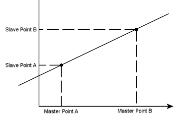
This command sets up an absolute linear gearing relationship between the master register and the position target for the axis this command was issued to (the slave axis) and will make the slave axis follow that relationship. Typically, the master register is the Target or Actual Position of another axis. This command is very useful for making an axis follow a reference input (half-axis).
When this command is issued, the slave axis must either already be at the correct point specified by the relationship based on the current value of the master, or a Transition command must previously have been issued to specify how the axis should move to get to the line. Notice that this means most applications will need to use the Transition command!
Master Point A, Master Point B, Slave Point A, and Slave Point B specify the linear relationship. The behavior beyond these points depends on the Endpoint Behavior parameter.

EndPoint Behavior
The Endpoint Behavior specifies what happens to the slave axis if the master moves outside of the range specified by Master Point A and Master Point B:
|
Option |
Description |
Image |
|
Fault |
If the master exceeds either endpoint, the slave axis' runtime error bit will be set which will halt the axis if the Auto Stops are configured to do so. |
|
|
Truncate |
If the master moves past an endpoint, the slave axis' Target Position will stop at the endpoint. When the master moves back into the range, the gearing will resume. If the master is moving quickly when it exceeds the endpoint, it may cause the slave to stop abruptly. Note:
|
|
|
Extrapolate |
The slave will always follow the master on the linear relationship. |
|
Related Commands
With the Gear Absolute command, the Target Position will follow the master value exactly. If the master is noisy, or exceeds the position, velocity, or acceleration limits of the slave axis, this can cause problems. In this case, consider using the Track Position (57) or Track Position (I-PD) (58) commands, which provide limits on the slave axis motion.
See the Gearing Overview topic for general information about gearing, including possible Gear Masters.
Specifying a Register Address
When issuing this command from anywhere other than RMCTools, the addresses in the Master Register command parameter must be entered as an integer value.
RMC addresses are represented in IEC format as:
%MDfile.element, where file = file number, and element = element number.
Use the following equation to convert a register address to integer format, N:
N = file * 4096 + element
Example:
Register address %MD8.33 is 8*4096 + 33 = 32801.
Target Generator State Bits
The Target Generator Done, State A and State B bits are all off during the gearing.
Pri. TG SI Busy (Primary Target Generator Superimposed Busy) Bit
This bit will be set during the transition. The transition begins when the motion command is issued, not necessarily when the Transition command is issued. When the transition completes, this bit will clear. At this point, the slave axis will be on the mapped relationship.
See Also
Gearing Overview | List of Commands | Commands Overview
Copyright © 2025 Delta Computer Systems, Inc. dba Delta Motion