Note: When positive voltage is sent to an axis’s drive, the axis must extend. The extend direction is defined as the direction that causes the transducer to return increasing counts.
Use shielded twisted pairs for all connections to inputs and outputs. Route the transducer wiring separate from other wiring. You must provide the power supplies needed by your transducers.
RMC SSI Input
Six-Pin Plug-in Terminal Block
|
Pin |
Function |
|
1 |
SSI Axis + Clock |
|
2 |
SSI Axis - Clock |
|
3 |
SSI Axis Common |
|
4 |
SSI Axis + Data |
|
5 |
SSI Axis - Data |
|
6 |
Case |
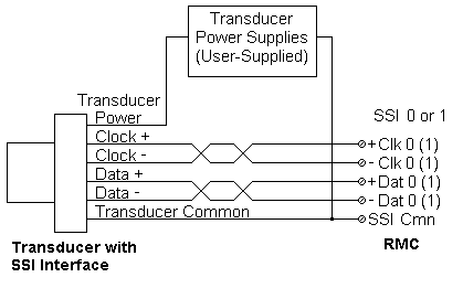
SSI uses differential line driver (RS422) clock and data signals. Connect both the +Clock and Clock between the RMC and transducer for the clock signal, and both the +Data and Data between the RMC and transducer for the data signal.
The power (+24V) and ground is not provided by the RMC, and therefore must be provided externally to the transducer.
Connect the transducer DC ground to SSI Cmn.

RMC Drive Outputs
Four-Pin Plug-in Terminal Block
|
Pin |
Function |
|
1 |
Axis 0 Drive |
|
2 |
Drive Common |
|
3 |
Axis 1 Drive |
|
4 |
Case |
When positive voltage is sent to an axis’s drive, the axis must extend. The extend direction is defined as the direction that causes the transducer to return increasing counts.
CAUTION: If the outputs from the RMC are reversed, the axis will be uncontrollable when power is connected. Confirm that your wiring is correct!
See also:
Copyright (c) 1997-2015 by Delta Computer Systems, Inc.