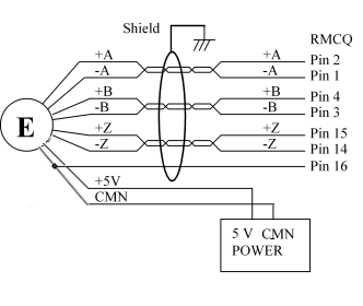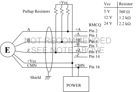
Use shielded twisted pairs for all connections to inputs and outputs. Route the quadrature encoder wiring separate from other wiring. You must provide the power supplies needed by your quadrature encoders.
CAUTION: If the drive outputs from the RMC are reversed, the axis will be uncontrollable when power is connected. Confirm that your wiring is correct!
DB25S Pin-out
Note: Color codes are for cable part number RMC-CB-QUAD-01. This cable has three wire groups: encoder, limits, and drive. The wire color column lists the wire group and the individual wire color within that group.
The encoder common should be connected to both wires listed.
|
Pin |
Function |
Wire Color |
Pin |
Function |
Wire Color |
|
1 |
A- |
Enc: white/blue |
14 |
Index (Z)- |
Enc: white/green |
|
2 |
A+ |
Enc: blue/white |
15 |
Index (Z)+ |
Enc: green/white |
|
3 |
B- |
Enc: white/orange |
16 |
Encoder Common |
Enc: brown/white |
|
4 |
B+ |
Enc: orange/white |
|
|
Enc: white/brown |
|
5 |
N/C |
|
17 |
N/C |
|
|
6 |
Retract Lim- |
Lim: white/orange |
18 |
Home- |
Lim: white/green |
|
7 |
Retract Lim+ |
Lim: orange/white |
19 |
Home+ |
Lim: green/white |
|
8 |
Extend Lim- |
Lim: white/blue |
20 |
Fault- |
Drv: white/green |
|
9 |
Extend Lim+ |
Lim: blue/white |
21 |
Fault+ |
Drv: green/white |
|
10 |
N/C |
|
22 |
N/C |
|
|
11 |
N/C |
|
23 |
N/C |
|
|
12 |
Drive* |
Drv: blue/white |
24 |
Enable*- |
Drv: white/orange |
|
13 |
Drive Common* |
Drv: white/blue |
25 |
Enable*+ |
Drv: orange/white |
*Outputs, all others are inputs
Encoder Wiring
5 Volt differential driver:

NPN Open Collector (NOT RECOMMENDED):
Note: Open collector encoders should only be used in lab environments with very little electrical noise and short wire runs.

Noise immunity can be improved in the diagram above by adding a capacitor across each RMC encoder input: from +A to -A, from +B to -B, and from +Z to -Z. Notice the capacitors are connected to the minus inputs even though no signal wires are connected there. The capacitor will limit the frequency response of the input. Some suggested capacitor values are listed along with the resultant frequency response limit:
|
Capacitor (µF) |
Frequency |
|
0.0047 |
1 MHz |
|
0.010 |
500 kHz |
|
0.022 |
200 kHz |
|
0.047 |
100 kHz |
|
0.10 |
50 kHz |
|
0.22 |
20 kHz |
|
0.47 |
10 kHz |
|
1.0 |
5 kHz |
Input Wiring (Home and Limits)
NPN Proximity sensors
Normally Open recommended for Home
Normally Closed recommended for Limits

PNP Proximity sensors
Normally Open recommended for Home
Normally Closed recommended for Limits

Drive Output Wiring

Fault Input Wiring
From TTL output:

From Open Collector Output:

Enable Output Wiring
To TTL input (high = enable):

To active low Enable input:

See also:
Copyright (c) 1997-2015 by Delta Computer Systems, Inc.