The QAx module can be wired to quadrature encoders. Each axis on the QAx also has a Fault input, Enable output, Control output, two high-speed registration inputs, and a high-speed home input. The pinout of each axis is identical.
Use shielded twisted pairs for all connections to inputs and outputs. Route the transducer wiring separate from other wiring. You must provide the power supplies needed by your transducers. See Wiring Guidelines for general wiring information.
NOTE:
The following example schematics do not include transducer pin numbers, color codes, or power supply requirements, since these vary between different transducers. To determine your power supply needs and connector pin-outs or cable color codes, consult your transducer manufacturer's documentation.
Pin-Out
The RMC-CB-QUAD-01-xx cable is an optional accessory for the QA module.
|
Pin # |
QA1 Label |
QA2 Label |
Function |
RMC-CB-QUAD-01-xx Wire Color |
|
1 |
A- |
A- |
A- from encoder (5 V) |
Enc: white/blue |
|
2 |
A+ |
A+ |
A+ from encoder (5 V) |
Enc: blue/white |
|
3 |
B- |
B- |
B- from encoder (5 V) |
Enc: white/orange |
|
4 |
B+ |
B+ |
B+ from encoder (5 V) |
Enc: orange/white |
|
5 |
n/c |
n/c |
No connection |
|
|
6 |
Reg Y/NegLim- |
RY/NL- |
Registration Y or Negative Limit (12-24 VDC) |
Lim: white/orange |
|
7 |
Reg Y/NegLim+ |
RY/NL+ |
Lim: orange/white |
|
|
8 |
Reg X/PosLim- |
RX/PL- |
Registration X or Positive Limit (12-24 VDC) |
Lim: white/blue |
|
9 |
Reg X/PosLim+ |
RX/PL+ |
Lim: blue/white |
|
|
10 |
n/c |
n/c |
No connection |
|
|
11 |
n/c |
n/c |
No connection |
|
|
12 |
Control Out |
CtrlOut |
Control Output |
Drv: blue/white |
|
13 |
Cmn |
Cmn |
Common |
Drv: white/blue |
|
14 |
Z- |
Z- |
Index pulse from encoder (5 V) |
Enc: white/green |
|
15 |
Z+ |
Z+ |
Enc: green/white |
|
|
16 |
Cmn |
Cmn |
Common |
Enc: white/brown |
|
17 |
n/c |
n/c |
No connection |
|
|
18 |
Home- |
Home- |
Home Input (12-24 VDC) |
Lim: white/green |
|
19 |
Home+ |
Home+ |
Lim: green/white |
|
|
20 |
FltIn- |
FltIn- |
Fault Input (12-24 VDC) |
Drv: white/green |
|
21 |
FltIn+ |
FltIn+ |
Drv: green/white |
|
|
22 |
n/c |
n/c |
No connection |
|
|
23 |
n/c |
n/c |
No connection |
|
|
24 |
EnOut- |
EnOut- |
Enable Output (12-24 VDC) |
Drv: white/orange |
|
25 |
EnOut+ |
Enout+ |
Drv: orange/white |
Encoder Wiring
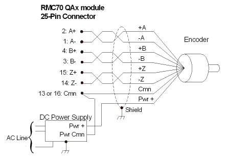
Quadrature Encoders
The QAx module A, B, and Z inputs accept only Differential Line Driver (RS-422) signals. Single-ended line drivers (TTL) are not supported due to low noise immunity. The user must supply power for the encoder.
The Cmn on the QA module must be connected to the encoder, or the signals will not be read correctly!
Daisy-Chaining A and B Quadrature Inputs
One quadrature encoder can typically output its signals to multiple QA modules. Use a daisy-chain topology, and add termination only to the last input. Incorrect termination will result in distorted signals and will cause incorrect transducer readings. Use the Input Termination Axis Parameter to set the termination. Termination is selectable on the A and B signals. The Z signal is always terminated with 120 Ω.
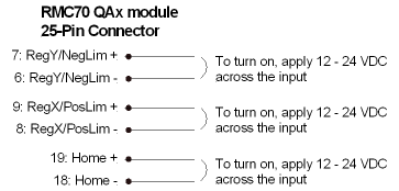
RegX/PosLim, RegY/NegLim, and Home Inputs
The Reg/Lim and Home inputs are compatible with signal levels from 12 to 24 V. They draw 2.7 mA max and turn on when the voltage across the input is greater than 6 V. The polarity is unimportant.
Fault Input Wiring
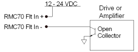
The Fault input is compatible with signal levels ranging from 12V to 24V. The Fault Input draws 2.7mA maximum and turns on at 6V. The Fault input turns on when a current flows. The polarity of the voltage is unimportant. See the Fault Input topic for more details.
Fault input wiring diagrams:
|
Generic:
|
From Open Collector Output:
|
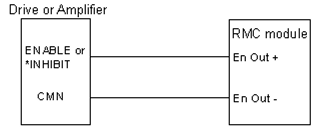
Enable Output Wiring
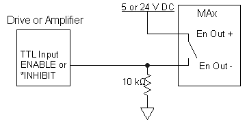
The Enable output is a solid state relay (SSR). When it is off, it has high impedance, and when on it has low impedance (10 Ω maximum). Because the Enable output is isolated, the user must power it externally. The maximum current and voltage for the Enable output is 100 mA and 30 V.
The Enable output has a + and - connection. Both lines must be connected for the output to function. Because both sides of the output are provided, the switches may be independently connected in a high side or low side configuration (that is, with the load (input) on the source or sinking side of the output). See the wiring diagrams below.
See the Enable Output topic for more details on the Enable Output.
To TTL input (high = enable):
To active low Enable input:
Using Outputs with Inductive Loads
External fuses should be used to protect the SSRs if there is a possibility of over-current. When switching inductive loads, it is important to place a diode or tranzorb across the load to protect the switch when transitioning from an “ON” to an “OFF” state. Otherwise, the collapsing magnetic field can cause a reverse voltage spike in excess of the 30 V rating of the SSR.
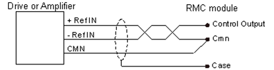
Control Output Wiring
The valve or motor drive connects to the following MAx pins:
|
Pin |
Function |
|
Control Output |
Control Output |
|
Cmn |
Control Output Common. Each axis has two Cmn pins. Either of the 2 pins may be used. |
See the Control Output topic for more details on the Control Output.
Note:
The Control Output polarity can be set with the Invert Output Polarity parameter.
See Also
Copyright © 2026 Delta Computer Systems, Inc. dba Delta Motion