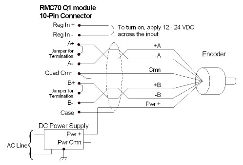
The Q1 expansion module can be wired to quadrature encoders.
Use shielded twisted pairs for all connections to inputs and outputs. Route the encoder wiring separate from other wiring. You must provide the power supplies needed by your encoders. See Wiring Guidelines for general wiring information.
Wire clamp screws must be tightened to max 7 b-in (0.8Nm).
NOTE:
The example schematics do not include transducer pin numbers, color codes, or power supply requirements, since these vary between different transducers. To determine your power supply needs and connector pin-outs or cable color codes, consult your transducer manufacturers documentation.
Pin-Out
|
Pin |
Function |
|
Reg In+ |
High-Speed Registration or Home Input (12 - 24 VDC) |
|
Reg In- |
|
|
A+ |
Encoder A Input (5 V differential) |
|
Jumper for Termination |
|
|
A- |
|
|
Quad Cmn |
Encoder Common |
|
B+ |
Encoder B Input (5 V differential) |
|
Jumper for Termination |
|
|
B- |
|
|
Case |
Connected to RMC Chassis |
Encoder Wiring
The Q1 module interfaces only to quadrature encoders with 5 V Differential Line Driver (RS-422) signals. Single-ended line drivers (TTL) are not supported due to low noise immunity.
Use twisted pairs and shielded cables for the A and B signals. Always install the termination jumper to maintain signal integrity. The termination jumper adds a 249Ω resistor between the + and - inputs.
The Reg input is compatible with signal levels from 12 to 24 V. It draws 2.7 mA max and turns on when the voltage across the input is greater than 6 V. The polarity is unimportant.
Diagram
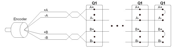
Daisy-Chaining Quadrature Inputs
One quadrature encoder can typically output its A and B signals to thirty-two (32) RMC75 Q1 modules. Use a daisy-chain topology as shown below. Do not use a star topology. Add termination only to the last input, as illustrated. Incorrect termination will result in distorted signals and will cause incorrect transducer readings.
See Also
Copyright © 2026 Delta Computer Systems, Inc. dba Delta Motion