
This topic covers the wiring of the analog inputs on the RMC150 Analog (A), Analog (G), Analog (H), and Universal I/O modules. For the Control Output (Drive) wiring, see the RMC150 Control Output (Drive) Wiring topic.
Use shielded twisted pairs for all connections to inputs and outputs. Route the transducer wiring separate from other wiring. You must provide the power supplies needed by your transducers. See Wiring Guidelines for general wiring information.
Wire clamp screws must be tightened to max 4.5 lb-in (0.51 Nm).
The commons are internally connected.
Note:
The example schematics do not include transducer pin numbers, color codes,
or power supply requirements, since these vary between different transducers.
To determine your power supply needs and connector pin-outs or cable color
codes, consult your transducer manufacturer's documentation.
Note:
The analog input Cmn pin must be
connected! A disconnected Cmn
pin can cause noise and inaccurate readings.
Note:
If the input is disconnected, input voltage will be pulled down ≤ -10V.
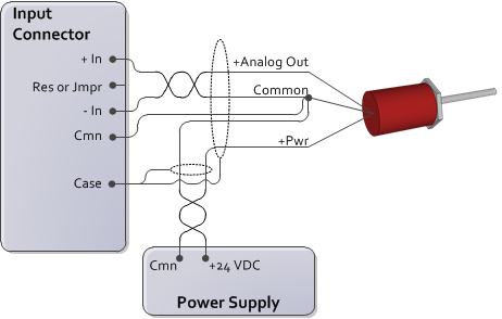
Voltage Input, 4- or 5-wire
To minimize electrical interference:
-In and Cmn must be connected. This connected should be made as close to the transducer as possible.
Use individually shielded twisted-pair wire.
Typically, the cable shield should be connected to earth on one end only.
If the transducer has only one common, connect the power supply and the RMC Cmn to it. For best results, make this connection at the transducer.
Voltage Input, 3-wire
To minimize electrical interference:
-In and Cmn must be connected. This connected should be made as close to the transducer as possible.
Use individually shielded twisted-pair wire.
Typically, the cable shield should be connected to earth on one end only.
Potentiometer
When using a potentiometer, use the Exciter pin, if the module has one, to increase the accuracy of the analog to digital conversion. Do NOT use the Exciter pin to power a transducer! The Exciter pin can source up to 8mA.
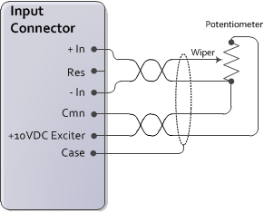
To minimize electrical interference:
-In and Cmn must be connected. This connected should be made as close to the potentiometer as possible.
Use individually shielded twisted-pair wire.
Typically, the cable shield should be connected to earth on one end only.
Current 4-20mA, 4 wire
Note:
The Analog
(G) Module does not support current feedback.
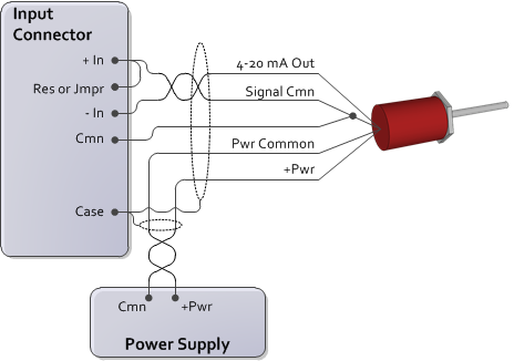
To minimize electrical interference:
-In and Cmn must be connected. This connected should be made as close to the transducer as possible.
Use individually shielded twisted-pair wire.
Typically, the cable shield should be connected to earth on one end only.
Current 4-20mA, 2-Wire
Note:
The Analog
(G) Module does not support current feedback.
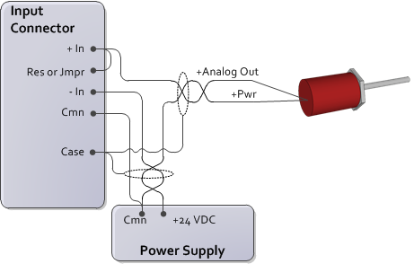
Notes:
The Res and -In pins are internally connected via a 250 Ohm resistor.
To minimize electrical interference, use individually shielded twisted-pair wire.
See Also
Wiring Guidelines | Analog (A) Module (RMC150) | Analog (G) Module (RMC150) | Analog (H) Module (RMC150) | Universal I/O (UI/O) Module (RMC150) | RMC150 Control Output (Drive) Wiring
Copyright © 2026 Delta Computer Systems, Inc. dba Delta Motion