This document will refer to the VC2124, but the same information applies to the VC2100.
To convert the RMC's ±10 V Control Output to current (such as for servo valves), use Delta's VC2124 or VC2100 voltage-to-current converter. Information on the VC2124 and VC2100 is available on Delta's website, https://deltamotion.com. This topic explains how to set up the RMC parameters to work with the VC2124 and VC2100:
Scaling ±10 V to Current Output (± mA)
To scale the ±10 V Control Output to a current range centered around 0, such as ±85mA, use the following procedure:
Set the VC2124 current range to the closest value equal to or greater than the current range required by the valve.
Calculate the Output Limit parameter using the following equation:
OutputLimit [V] = (Desired Limit[mA] * 10) / VC2124 current setting
Example:
Consider a servo valve that requires ±85 mA:
1. Set the VC2124 to ±90 mA.
2. Calculate the Output Limit:
OutputLimit [V] = ( 85[mA] * 10 ) / 90[mA]
Output Limit = 9.444 [V]
Scaling ±10 V to 4-20 mA (RMC75 and RMC150)
If you are using an RMC module that only supports a ±10 V output together with a valve or drive that requires a 4-20mA input, follow these steps to set up the RMC parameters to work together with the VC2124 to produce a 4-20 mA output.
Set the VC2124 current range to ±20 mA.
Set the Output Scale to: 4 V/100%
Set the Output Bias to: 6 V.
Set the Output Limit to: 4 V. (prevents the output from going below 4mA):
Inverting the Output
If a positive voltage makes the system move the wrong direction, you will need to invert the output. To do so, do steps 1-4 above, but set the Invert Output Polarity bit and set the Output Bias to -6 V.
The mathematical reasoning is as follows:
After setting the VC2124 to ±20 mA, the next step is to scale the ±100% PFID output to 2-10V (the VC2124 will then convert the 2-10 V to 4-20 mA). Use the equation y=mx+b, where
y = 2-10 V range
x = ±100% range
m = Output Scale [V/100%]
b = Output Bias [V]
To calculate the Output Scale and Output Bias:
Output Scale = m = (y1 - y0)/(x1-x0) = (10-2)/100 - (-100)) = 8[V]/200[%]
Output Scale = 4 [V/100%]
Output Bias = y1 - m * x1 = 10[V] - 4[V/100%] * 100[%]
Output Bias = 6 [V]
For different output ranges, use the same method to calculate the parameters.
Scaling ±10 V to 4-20 mA (RMC200)
If you are using an RMC module that only supports a ±10 V output together with a valve or drive that requires a 4-20mA input, follow these steps to set up the RMC parameters to work together with the VC2124 to produce a 4-20 mA output.
Set the VC2124 current range to ±20 mA.
Set the Voltage at 100% to: 10 V
Set the Voltage at 0% to: 6 V
Set the Voltage at -100% to: 2 V
Inverting the Output
If a positive voltage makes the system move the wrong direction, you will need to invert the output. To do so, swap the values of Voltage at 100% and Voltage at -100%.
Wiring
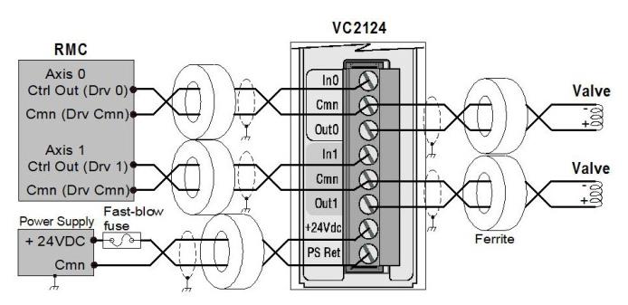
VC2124
Fuse 24 VDC input with 5A maximum, UL-listed, fast-blow fuse. One fuse suffices for up to 10 VC2124s. For maximum protection, use one 500mA fuse per VC2124.
For noise immunity, use twisted, shielded pairs for all connections (twisted pair with overall shield is acceptable). For best noise immunity and CE compliance, keep wires from the RMC to the VC2124 as short as possible and less than 98 ft (30 m), and place ferrites on all cables as close to the VC2124 as possible. Sample ferrite part numbers from Steward: 28A2029-0A0 or 0A2, 28A5131-0A2, 28A0593-0A2, 28A0807-0A2, 28A3851-0A2, 28A2024-0A0 or 0A2.
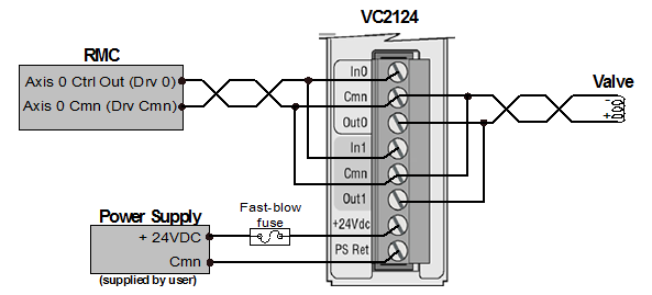
VC2124 Parallel Outputs
To achieve 200 mA output, wire the two channels in parallel as indicated here:
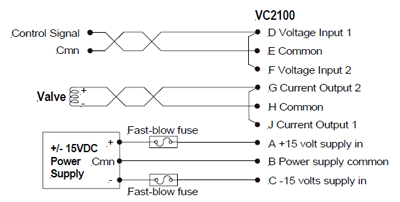
VC2100
Fuse the ±15 VDC inputs with 5 A maximum, UL-listed, fast-blow fuses. For maximum protection, use two 500 mA fuses per VC2100.
For noise immunity, use twisted, shielded pairs for all connections (twisted pair with overall shield is acceptable). For best noise immunity, keep wires from the RMC to the VC2100 as short as possible and less than 98 ft (30 m), and place ferrites on all cables as close to the VC2100 as possible. Sample ferrite part numbers from Steward: 28A2029-0A0 or 0A2, 28A5131-0A2, 28A0593-0A2, 28A0807-0A2, 28A3851-0A2, 28A2024-0A0 or 0A2.
VC2100 Parallel Outputs
To achieve 200 mA output, wire the two channels in parallel as indicated here:
See Also
Output Bias | Output Scale | Control Output
Copyright © 2026 Delta Computer Systems, Inc. dba Delta Motion