Open topic with navigation
Filtering
Filtering can be used to smooth values. A noisy position feedback or Control Output signal will be smoother if filtering is applied.
Filtering increases the phase delay in the filtered value, meaning the signal becomes delayed. Phase delay on the feedback can be detrimental to control, especially if the system must respond quickly. Therefore, feedback filtering on control axes should be used only when necessary.
Filtering can be especially useful on reference axes. For example, consider a control axis that is geared to a reference axis. The reference axis is controlled by a potentiometer. When the operator turns the potentiometer, it produces a fairly noisy signal. The axis that is geared to this noisy signal will, in turn, produce jerky motion. To smooth the motion, a filter can be applied to the reference Actual Position.
|
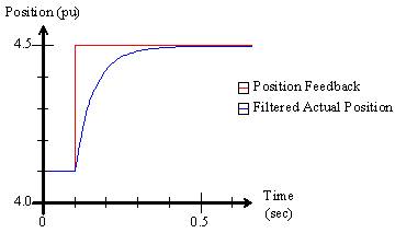
For example, suppose the position feedback makes a step jump from 4.1 to 4.5 position units. With the position filter disabled (set to zero), the Actual Position would also make a step jump. By applying a filter, the Actual Position is filtered, and does not make a step jump.
|
|
The RMC offers filtering in the following places:
-
Feedback Filter (Input Filter)
The feedback inputs such as position, velocity, acceleration, pressure, force, etc. can be filtered. Filtering the feedback can improve control if the feedback is noisy or has quantization errors. However, feedback filtering must be used with caution to avoid phase delay.
Feedback filtering may be applied to the values used by the control algorithm, or only to the values displayed to the user, or to both. By default, the velocity and acceleration display values are filtered since they normally have a lot of quantization error.
The feedback filtering options differ between the RMC75/150 and the RMC200. See the RMC75/150 Feedback Filtering and RMC200 Feedback Filtering sections below.
-
Output Filter
The Output Filter filters the Control Output components contributed by the Proportional, Differential, and Double Differential gains. Filtering the output can overcome the negative effects of quantization error on the values derived from the feedback, for example, velocity and acceleration, or the pressure rate or force rate.
The Output Filter can provide great improvement in control in conjunction with the Differential and Double Differential gains, especially for systems that tend to oscillate. For details on how to use the Output Filter, see the Tuning procedures, such as Tuning Position.
Filter Algorithm Types
The RMC's offer various filter algorithms, such as first order, Butterworth, ABG, etc. For a description of each filter types, and where each type may be applied in each RMC, see the Filter Algorithm Types topic.
RMC75/150 Feedback Filtering
The RMC75 and RMC150 provide a 4-pole Butterworth filter for the feedback.
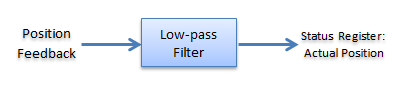
Position Filtering
The position filtering will apply to the value the control algorithm uses and to the value that is displayed.
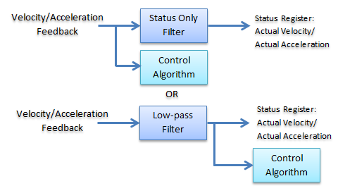
Velocity and Acceleration Filtering
The velocity and acceleration filters can be selected to apply only to the displayed value, or to the value that the control algorithm uses, which will then be the displayed value as well.
To Apply Display Filtering:
Setting the display filtering means you are filtering only so that the values are easier to see on a plot, or so that a displayed number doesn't jump around so much.
-
Make sure the Velocity Filter Type and Acceleration Filter Type are set to Status Only.
-
Set the Actual Velocity Filter and/or Actual Acceleration Filter values to the desired cut-off frequencies:
-
Start with a large value, such as 100 or 200 Hz.
-
Decrease the number to apply heavier filtering. A lower number provides heavier filtering. A value of zero means the filter is off.
-
Do not use the Actual Position filter, since it always applies to the value used by the control algorithm.
To Apply Filtering on the Controlled Signal:
If the feedback is so noisy that it is causes problems for the control algorithm, you may need to filter it. The displayed value will be the same as that filtered value. The RMC75/150 use the 4-pole Butterworth that has a large phase delay, which can cause large oscillations if not carefully applied.
-
In the Axis Tools, on the All tab, in the Feedback or Secondary Feedback section, expand the Filtering/Modeling section.
-
Make sure the Velocity Filter Type and Acceleration Filter Type are set to Low Pass.
-
Set the Actual Position Filter, Actual Velocity Filter and/or Actual Acceleration Filter values to the desired cut-off frequencies:
-
Start with a large value, such as 100 or 200 Hz.
-
Decrease the number to apply heavier filtering. A lower number provides heavier filtering. A value of zero means the filter is off.
Velocity Feedback
The velocity feedback filtering is identical to the position feedback filtering, except that the position filter is of course not available, and the Model is not available.
Pressure/Force Feedback
The RMC75 and RMC150 provide a 4-pole low-pass Butterworth filter for the pressure or force feedback as follows:
RMC200 Feedback Filtering
The RMC200 supports the following feedback filters:
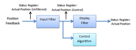
Input Filter: Applies to the control algorithm and offers several filter algorithm types. The default setting for this filter is off.
Display Filter: Filters the value that has already been filtered by the input filter. This filter is a fourth-order Butterworth filter. The default setting is that the display filter is applied to velocity and acceleration.
Status Registers
The RMC200 Axis status registers for feedback include:
These status registers are useful for troubleshooting and for determining the effectiveness of the filtering.
To Apply Display Filtering Only:
Setting the display filtering means you are filtering only so that the values are easier to see on a plot, or so that a displayed number doesn't jump around so much, and not affecting the feedback values used by the control algorithm.
-
In the Axis Tools, on the All tab, in the Feedback or Secondary Feedback section, expand the Input Filter section.
-
Set the Input Filter Type to None.
-
In the Display Filter section, set the Position Display Filter, Velocity Display Filter and/or Acceleration Display Filter values to the desired cut-off frequencies:
-
Start with a large value, such as 100 or 200 Hz.
-
Decrease the number to apply heavier filtering. A lower number provides heavier filtering. A value of zero means the filter is off.
To Apply Filtering on the Controlled Signal:
If thefeedback is so noisy that it is causes problems for the control algorithm, you may need to filter it. The RMC200 has many options for filtering the signal used for control.
-
In the Axis Tools, on the All tab, in the Feedback or Secondary Feedback section, expand the Input Filter section.
-
Set the Input Filter Type parameter to the desired filter.
-
Set the Position Input Filter, Velocity Input Filter, and/or Acceleration Input Filter values to the desired cut-off frequencies:
-
Start with a large value, such as 100 or 200 Hz. For the ABG and ABGD filters, start with the maximum allowed value as described in the Filter Algorithm Types topic.
-
Decrease the number to apply heavier filtering. A lower number provides heavier filtering. A value of zero means the filter is off.
-
In the Display Filter section, you may choose whether or not to also apply a display filter. To turn off the display filtering, set the Position Display Filter, Velocity Display Filter and/or Acceleration Display Filter values to zero.
Velocity Feedback
The velocity filtering is identical to the position filtering, except that the position filter is of course not available, and the Model is not available.
Pressure/Force Feedback
For pressure and force axes, the RMC200 provides the same options as for position axes, except that there is only an Actual Pressure/Force and an Actual Pressure/Force Rate, and the Model is not available.
See Also
Filter Algorithm Types | Modeling | Control Features Overview
Send comments on this topic.
Copyright © 2026 Delta Computer Systems, Inc. dba Delta Motion