See the Commands Overview topic for basic command information and how to issue commands from PLCs, HMIs, etc.
Command Parameters
|
# |
Parameter Description |
Data Type |
Range |
|---|---|---|---|
|
1 |
Curve ID |
Internal: DINT External: REAL |
0-50000 |
|
2 |
Curve Data (address) Note: See Specifying a Register Address below. |
REAL |
any Variable Table address |
|
3 |
Interpolation Method
|
REAL |
a valid integer as described |
|
4 |
Life Cycle
|
REAL |
a valid integer as described |
Description
This command is used for creating curves in the RMC from a PLC, PC, or even from user programs. For details on the procedure, see Creating Curves Using the Curve Add Command. This command is not necessary when creating curves in the Curve Tool. Once the curve data has been written to the Variable Table, sending this command will create the curve in the RMC.
Once a curve has been created, it can be viewed in the Curve Tool, and can be used with the Curve Start (86) or Curve Start (Prs/Frc) (87) command for a time-based profile or camming based on a master.
Creating a curve requires some processing time that typically exceeds one loop time. It is important to not start a curve before it has been processed and added to the Curve Store. The RMC will report the state of the Curve Add in the Curve Status register, which is part of the Curve Data.
If adding a curve results in a curve being overwritten, any axes currently following the overwritten curve will continue to follow the original curve until the curve motion completes, another motion command is sent to the axis, or the axis halts.
For more details, refer to the Creating Curves Using the Curve Add Command topic.
Curve ID
This provides a way of identifying the curve. This can be any number from 0 to 50,000. The ID will be used in the Curve Start (86) and Curve Start (Prs/Frc) (87) commands to specify which curve to start. A maximum of 128 curves can be stored in the Curve Store, although each ID can be from 0 to 50,000. For the Multiple Curves format, the curves will receive sequential IDs beginning with this Curve ID.
If a curve with the requested ID already exists, the existing curve will be deleted and the new curve with that ID added.
Curve Data
The Curve Data parameter specifies the starting address of the curve data in the Variable Table. For details on the curve data, see the Curve Data Formats topic.
For all the Curve Formats, the first item in the curve data is the Curve Status. Because it is the first item, the Curve Status is located at the address specified by the Curve Data parameter. The RMC reports the state of the curve processing in this Curve Status register. Adding a curve requires some processing time that typically exceeds one loop time. It is important to not try to use a curve until it has been processed and added to the Curve Store. When the Curve Status is 3, the curve has been added to the Curve Store and is ready to use.
The following Curve Status values are defined:
Interpolation Method
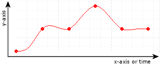
For the Interpolation Method parameter, choose from one of the methods below. The Cubic (2) method is the most common method and creates the smoothest motion.
Cubic (2)
The curve will smoothly go through all points. This is the most common interpolation method. This method will create smooth motion.
On position axes, the Velocity Feed Forward and Acceleration Feed Forward will apply to cubic interpolated curves, but higher order gains should not be used, such as the Jerk Feed Forward, Double Differential Gain, and Triple Differential Gain.
On pressure or force axes, the Pressure/Force Rate Feed Forward will apply.
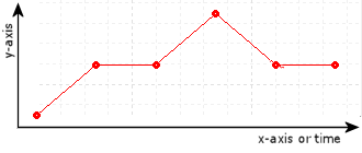
Linear (1)
The curve will consist of straight-line segments between each point. Because the velocity is not continuous, a position axis will tend to overshoot at each point. This type of curve is typically more suitable for pressure or force axes.
On position axes, the Target Acceleration will always be zero. Therefore, the Acceleration Feed Forward will have no effect for linear interpolated curves.
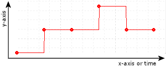
Constant (0)
The curve will consist of step jumps to each point. The curve will not be continuous. This method is seldom used, but may be useful in applications where step jumps are desired, such as some blow-molding systems. This method requires that the axis not be tuned very tightly, or the axis may oscillate and Output Saturated errors may occur. The Position I-PD control algorithm is recommended for following constant interpolated curves.
On position axes, the Target Velocity and Target Acceleration will always be zero. Therefore, the Velocity Feed Forward and Acceleration Feed Forward will have no effect for constant interpolated curves.
On pressure or force axes, the Target Rate will always be zero. Therefore, the Pressure/Force Rate Feed Forward will have no effect for constant interpolated curves.
Determines how long the curve is stored:
Standard (0)
Added to curve store, but will not be saved to flash. Must be manually deleted. Standard curves will not be included in the upload or download in the Curve Tool, but can be viewed in the Curves in Controller window.
Start-Once (1)
Added to curve store, but will not be saved to flash. This curve will be deleted automatically as soon as an interpolation of this curve has been started, but the curve will continue to be executed correctly. Start-Once curves will not be included in the upload or download in the Curve Tool, but can be viewed in the Curves In Controller window.
Complete-Once (2)
Added to curve store, but will not be saved to flash. This curve may be deleted manually, but will also be deleted automatically once an interpolation of this curve has been started and completed to the end of the curve (indicated by when the Target Generator Done bit turns on). Complete-Once curves will not be included in the upload or download in the Curve Tool, but can be viewed in the Curves in Controller window.
Notice that if the Life Cycle is set to Complete-Once, but the curve is run with infinite cycles (Cycles = 0), the curve will never complete and therefore, will not automatically delete.
Permanent (3)
Added to curve store, and will be saved to Flash when Flash is updated. Must be manually deleted. Permanent curves will be included in the upload or download in the Curve Tool.
Specifying a Register Address
When issuing this command from anywhere other than RMCTools, the addresses in the Curve Data command parameter must be entered as an integer value.
RMC addresses are represented in IEC format as:
%MDfile.element, where file = file number, and element = element number.
Use the following equation to convert a register address to integer format, N:
N = file * 4096 + element
Example:
Register address %MD8.33 is 8*4096 + 33 = 32801.
See Also
Curves Overview | Curve Start (86) | Curve Start (Prs/Frc) (87) | Creating Curves Using the Curve Add Command | Creating Large Curves using the Curve Add Command | Curve Status Error Codes | Curve Delete (83) | Curve Delete All (85) | Curve Delete Except (84)
Copyright © 2026 Delta Computer Systems, Inc. dba Delta Motion