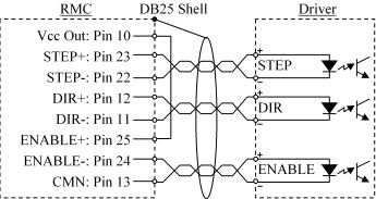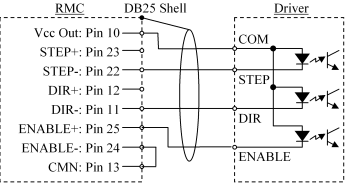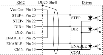
Use shielded twisted pairs for all connections to inputs and outputs. Route the quadrature encoder wiring separate from other wiring. You must provide the power supplies needed by your quadrature encoders and drives, although the RMC can provide +5 VDC for the optoisolators on the drive module as shown in the Stepper Output Wiring section below.
DB25S Pin-out
|
Pin |
Function |
Pin |
Function |
|
1 |
A- |
14 |
Index (Z)- |
|
2 |
A+ |
15 |
Index (Z)+ |
|
3 |
B- |
16 |
Encoder Common |
|
4 |
B+ |
17 |
N/C |
|
5 |
N/C |
18 |
Home- |
|
6 |
Retract Lim- |
19 |
Home+ |
|
7 |
Retract Lim+ |
20 |
Fault- |
|
8 |
Extend Lim- |
21 |
Fault+ |
|
9 |
Extend Lim+ |
22* |
Step- |
|
10* |
Vcc Out |
23* |
Step+ |
|
11* |
Direction- |
24* |
Drive Enable- |
|
12* |
Direction+ |
25* |
Drive Enable+ |
|
13* |
Drive Common |
|
|
*Outputs, all others are inputs
See also General Wiring Information.
Stepper Output Wiring
Note: Do not use Vcc Out to power your encoder because:
- This output’s voltage is not regulated.
- 50 mA is not adequate current to power the encoder. Each of the encoder outputs (A, B, and Z) requires 20 to 25 mA in addition to the current used by the encoder’s internal circuit.
- Using this output to power the encoder would violate the isolation that exists between the inputs and outputs.
Note: The STEP and DIR outputs are generated by a differential driver, but the ENABLE output is a relay. Therefore, power must be provided through the ENABLE output, as shown in the diagrams below.
Drive with bipolar inputs:

Drive with common anode inputs:

Drive with common cathode inputs:

Input Wiring
The wiring for all inputs is identical to the wiring for the quadrature interface module with analog outputs. See Quadrature Wiring for diagrams on these inputs.
See also:
Copyright (c) 1997-2015 by Delta Computer Systems, Inc.