This is part 2 of the complete step-by-step example of setting up and tuning a position/pressure axis.
Part 2: Tuning position.
Now the system is set up and ready to tune for position. The procedure in Tuning a Position Axis is followed:
Issue Open Loop (O) commands with small positive and negative drives to see if the cylinder goes in the right direction.
If the cylinder moves in the wrong direction, the wiring to the drive may be swapped, or Reverse Drive mode can be selected in the Config word.
Check the deadband. This system has a very small deadband, approx 5 millivolts, so we will not worry about it.
Set the gains and feed forwards to zero and issue a Set Parameters (P) command.
Double-click the Axis 0 Auto Stop word (in the Parameters field).
Set the Overdrive, Integrator Windup and Overdrive bits to Status only. Note that is possible only on systems where safety is not important.
Set the proportional gain to a small value, such as 5. Issue a Set Parameters (P) command.
Set the Plot Time for Axis 0 to 4.
Now make a move. The tuning process will consist of repeatedly making moves. To easily make repeated moves, use Stored Commands.
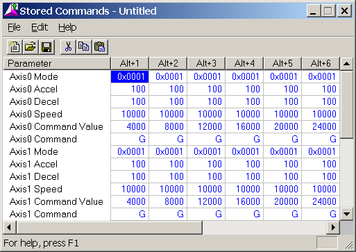
To edit and view the Stored Commands, click Stored Command Editor on the Stored Commands menu. The following window appears:

For example, ALT-1 on axis 0 will issue a Go cmd to 4000 at a speed of 2 in/sec, with acceleration rates of 10 in/(sec*sec). These are common initial values for moving hydraulic systems. Thes values are editable from this window.
To use the stored commands, click on any Axis 0 field, then press e.g. ALT-1 to move to 4 in. and ALT-5 to move to 20 in. The command will be issued to the axis where the cursor is located.
Using the Stored Commands, a move is made in this example from 2 in. to 8 in. The move will take less time than what the Plot Time is set to so that the entire move can be viewed.
After making the move, press the Insert key. This opens the Plot window with the last move. It looks like this:
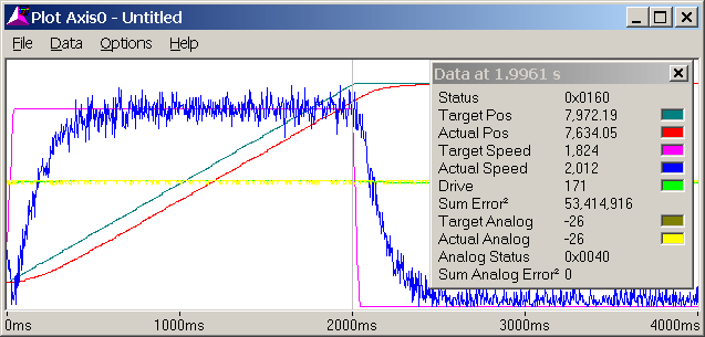
The detail window in the plot may be opened by clicking Show Detail Window on the Data menu. The detail window provides much useful information.
In this plot, the colored lines represent:
Red Actual Position
Dark Blue-Green Target Position (Desired Position)
Blue Actual Speed
Pink Target Speed
Green Drive Output (volts)
Yellow Pressure
Note the Sum Error Squared. This number gives an indication of the position error throughout the entire move. If the same move is repeated, this value can be compared to previous moves to determine whether the control has improved or worsened. If the number decreases, the control has improved.
If the system controls fairly well, which this one does, increase the speed. Here it is increased to 20.000 in/sec. The plot time can also be reduced to 2.
Increase the proportional gain until some oscillation appears, then back off 10-20%. On this system that point is about 70. The plot looks like this:
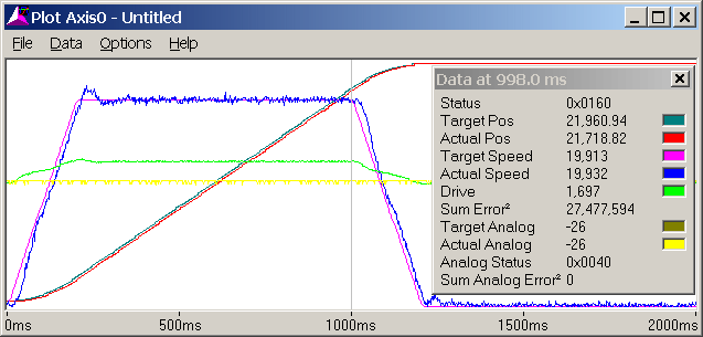
The Sum Error Squared decreased from 53 million to 27 million.
The position lags during the constant speed portion of the move, which the next step will address.
Make a fairly long move without any oscillations. After the move has completed, issue a Feed Forward Adjust (F) command. The Extend Feed Forward value is automatically updated to 84 in this case.
Make a move in the opposite direction. Issue a Feed Forward Adjust (F) command. The Retract Feed Forward value is automatically updated to 84 in this case.
Make a move. The axis should track much better now:
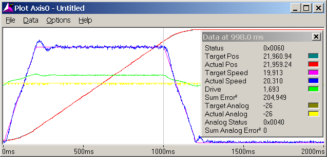
The Sum Error Squared decreased from 27 million to 204,000!
The next step is the integral gain. Gradually increase it as long as it does not adversely affect the system. Generally, the Integral gain does not need to be extremely high. In this example, 150 was deemed enough. The plot (not shown) did not change much from the previous one. This does not mean the integral gain won't help! It is important for dynamic changes that may be encountered during system operation and may not be present during the tuning.
Increase the Differential Gain. In this example, it was increased to 250. When the Differential gain is high enough, the drive output may look fuzzy:
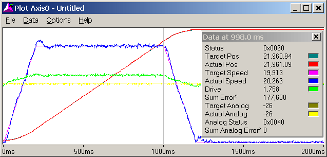
If the system starts oscillating or chattering, decrease the Differential Gain.
The Sum Error Squared decreased to 177,000.
Increase the Acceleration Feed Forwards to get rid of the following errors during acceleration and deceleration.
After increasing the Acceleration Feed Forwards to 200, the plot looks like this:
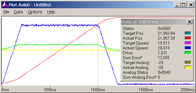
The Sum Error Squared decreased to 13,000!
The overshoot disappeared.
The Extend and Retract Feed Forwards are generally not the same for hydraulic systems.
The position is now tuned. To check that this will work at higher speeds, increase the Accel and Decel to 300 and the speed to 40000. The plot (plot time = 1 sec) looks like this:
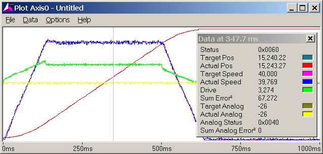
The parameters work well for the higher speed (no lagging, overshoot or oscillation), and will be left unchanged.
The Sum Error Squared increased, but that is only because of the higher speed, which inherently results in greater position errors.
This example is continued in the next topic.
Copyright (c) 1997-2015 by Delta Computer Systems, Inc.