The S8 Module can be wired to transducers with SSI interfaces or the magnetostrictive (MDT) Start/Stop and PWM interfaces. Use shielded twisted pairs for all connections to inputs and outputs. Route the transducer wiring separate from other wiring. You must provide the power supplies needed by your transducers.
See Wiring Guidelines for general wiring information.
Pin-Out
Terminal Block 1 (top)
|
Description |
|
Pin |
|
Description |
|
|
Input 0 Interrogate+ or Clock + |
Int/Clk0+ |
1 |
2 |
Ret/Dat0+ |
Input 0 Return+ or Data + |
|
Input 0 Interrogate- or Clock - |
Int/Clk0- |
3 |
4 |
Ret/Dat0- |
Input 0 Return- or Data - |
|
Input 0 Shield Connection |
Case |
5 |
6 |
Cmn |
Input 0 Common |
|
Input 1 |
Int/Clk1+ |
7 |
8 |
Ret/Dat1+ |
Input 1 |
|
Int/Clk1- |
9 |
10 |
Ret/Dat1- |
||
|
Case |
11 |
12 |
Cmn |
||
|
Input 2 |
Int/Clk2+ |
13 |
14 |
Ret/Dat2+ |
Input 2 |
|
Int/Clk2- |
15 |
16 |
Ret/Dat2- |
||
|
Case |
17 |
18 |
Cmn |
||
|
Input 3 |
Int/Clk3+ |
19 |
20 |
Ret/Dat3+ |
Input 3 |
|
Int/Clk3- |
21 |
22 |
Ret/Dat3- |
||
|
Case |
23 |
24 |
Cmn |
||
All the Cmn pins in Terminal Blocks 1 and 2 are internally connected.
Terminal Block 2 (bottom)
|
Description |
|
Pin |
|
Description |
|
|
Input 4 |
Int/Clk4+ |
1 |
2 |
Ret/Dat4+ |
Input 4 |
|
Int/Clk4- |
3 |
4 |
Ret/Dat4- |
||
|
Case |
5 |
6 |
Cmn |
||
|
Input 5 |
Int/Clk5+ |
7 |
8 |
Ret/Dat5+ |
Input 5 |
|
Int/Clk5- |
9 |
10 |
Ret/Dat5- |
||
|
Case |
11 |
12 |
Cmn |
||
|
Input 6 |
Int/Clk6+ |
13 |
14 |
Ret/Dat6+ |
Input 6 |
|
Int/Clk6- |
15 |
16 |
Ret/Dat6- |
||
|
Case |
17 |
18 |
Cmn |
||
|
Input 7 |
Int/Clk7+ |
19 |
20 |
Ret/Dat7+ |
Input 7 |
|
Int/Clk7- |
21 |
22 |
Ret/Dat7- |
||
|
Case |
23 |
24 |
Cmn |
||
All the Cmn pins in Terminal Blocks 1 and 2 are internally connected.
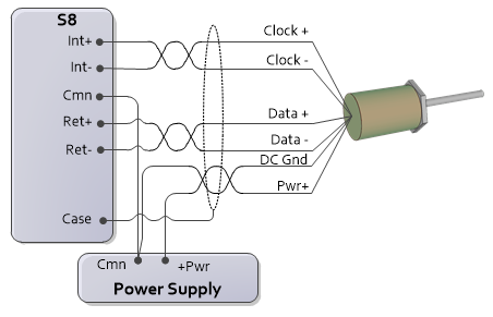
SSI Wiring
SSI uses differential line driver (RS422) clock and data signals.
Wiring Instructions
Connect the transducer DC ground to the S8 Cmn. The Cmn must be connected to the transducer, or the signals will not be read correctly!
The transducer power supply is not provided by the RMC. The user must supply a power supply. The power supply common may be connected to the same common that is connected to the RMC power supply Cmn.
Max Cable Length
|
Clock Rate |
Maximum Cable Length* |
|
100 kHz |
2100 ft (640 m) |
|
150 kHz |
1360 ft (415 m) |
|
230 kHz |
850 ft (255 m) |
|
250 kHz |
770 ft (235 m) |
|
375 kHz |
475 ft (145 m) |
|
500 kHz |
325 ft (99 m) |
|
921 kHz |
120 ft (37 m) |
|
971 kHz |
110 ft (34 m) |
|
1000 kHz |
100 ft (30 m) |
|
1500 kHz |
25 ft (7.5 m) |
|
2500 kHz |
3 ft (1 m) |
* The cable lengths are approximate, and may be affected by the type of wire and transducer.
SSI Monitor Mode
SSI Monitor Mode normally requires daisy-chaining the SSI wiring. When wiring a daisy-chained SSI system, the SSI master should be on one end of the daisy chain with the SSI device on the other end, and any monitoring modules in the middle of the daisy chain.
Wire the SSI device to the first monitoring RMC as illustrated in the diagram above, then daisy chain the first RMC to the other RMCs. Apply termination only to the SSI master.
Termination
SSI signals need to be terminated at the input end. For a typical RMC SSI input that is connected directly to an SSI device (the transducer or encoder), the ±Data signals are an input to the RMC, and need to be terminated. The ±Clock signals are an outputs from the RMC, so ±Clock termination on the RMC side doesn't apply.
For SSI Monitor, both the ±Data and ±Clock are inputs, so any termination applies to both ±Data and ±Clock. If the SSI Monitor is in the middle of a daisy-chained SSI configuration, it should not have termination, and only the last input in the chain should have termination. If the SSI Monitor is the endpoint of the wiring, then termination should be applied.
For channels configured as SSI input, after assigning the input to an axis, the SSI Termination parameter will be available on the All tab in the Axis Parameters Pane, in the Feedback section.
Magnetostrictive (MDT) Start/Stop and PWM Wiring
The S8 module interfaces only to transducers with Differential Line Driver (RS422) signals. The transducer pin names may vary by manufacturer.
|
Pin |
Function |
Possible Manufacturer Designation |
|
Int/Clk+ |
MDT Interrogation+ |
Interrogate+ Input |
|
Int/Clk- |
MDT Interrogation- |
Interrogate- Input |
|
Cmn |
MDT Common |
|
|
Ret/Dat+ |
MDT Return+ |
Pulse+ Output |
|
Ret/Dat- |
MDT Return- |
Pulse- Output |
|
Case |
Shield Connection |
|
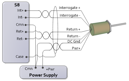
Wiring instructions:
Connect the transducer DC ground to Cmn. Each axis has two Cmn pins. Either of the 2 pins may be used. The Cmn must be connected to the transducer, or the signals will not be read correctly!
The transducer power supply is not provided by the RMC. The user must supply a power supply. The power supply common may be connected to the same common that is connected to the RMC power supply Cmn.
Quadrature Wiring
The S8 module interfaces only to encoders with 5V Differential Line Driver (RS-422) signals.
|
Pin |
Function |
|
Ret/Dat 6+ |
A+ |
|
Ret/Dat 6- |
A- |
|
Int/Clk 6+ |
unused |
|
Int/Clk 6- |
unused |
|
Ret/Dat 7+ |
B+ |
|
Ret/Dat 7- |
B- |
|
Int/Clk 7+ |
unused |
|
Int/Clk 7- |
unused |
|
Cmn |
common |
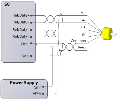
Wiring instructions:
Connect the encoder DC ground to any Cmn pin on the S8 module. The Cmn must be connected to the encoder, or the signals may not be read correctly!
The encoder power supply is not provided by the RMC. The user must supply a power supply. The power supply common may be connected to the same common that is connected to the RMC power supply Cmn.
See Also
Copyright © 2026 Delta Computer Systems, Inc. dba Delta Motion