This topic covers the wiring of the RMC200 LC8 Module. See Wiring Guidelines for general wiring information.
Pin-Out
Terminal Block 1 (top)
|
Description |
|
Pin |
|
Description |
|
|
6.75 V Exciter output |
+ExcA |
1 |
2 |
In0+ |
Input 0 + |
|
Input 0 Exciter - |
-ExcA |
3 |
4 |
In0- |
Input 0 - |
|
Input 0 Shield connection |
Case |
5 |
6 |
S0 |
Sense - |
|
Input 1 |
+ExcA |
7 |
8 |
In1+ |
Input 1 |
|
-ExcA |
9 |
10 |
In1- |
||
|
Case |
11 |
12 |
S1 |
||
|
Input 2 |
+ExcA |
13 |
14 |
In2+ |
Input 2 |
|
-ExcA |
15 |
16 |
In2- |
||
|
Case |
17 |
18 |
S2 |
||
|
Input 3 |
+ExcA |
19 |
20 |
In3+ |
Input 3 |
|
-ExcA |
21 |
22 |
In3- |
||
|
Case |
23 |
24 |
S3 |
||
Exciter Outputs: +6.75Vdc, 80mA per terminal block.
Terminal Block 2 (bottom)
|
Description |
|
Pin |
|
Description |
|
|
Input 4 |
+ExcB |
1 |
2 |
In4+ |
Input 4 |
|
-ExcB |
3 |
4 |
In4- |
||
|
Case |
5 |
6 |
S4 |
||
|
Input 5 |
+ExcB |
7 |
8 |
In5+ |
Input 5 |
|
-ExcB |
9 |
10 |
In5- |
||
|
Case |
11 |
12 |
S5 |
||
|
Input 6 |
+ExcB |
13 |
14 |
In6+ |
Input 6 |
|
-ExcB |
15 |
16 |
In6- |
||
|
Case |
17 |
18 |
S6 |
||
|
Input 7 |
+ExcB |
19 |
20 |
In7+ |
Input 7 |
|
-ExcB |
21 |
22 |
In7- |
||
|
Case |
23 |
24 |
S7 |
||
Exciter Outputs: +6.75Vdc, 80mA per terminal block.
General LC8 Wiring Guidelines
Isolation
Inputs 0-7 are isolated as a single group. There is no isolation between
inputs.
Maximum Excitation
Current
The total excitation current per terminal block does not exceed 80 mA.
The 6.75 V excitation is intended to work with 350 ohm load cells. Load
cells with lower resistance are supported, as long as the total excitation
current per terminal block does not exceed 80 mA.
Shielding
Wire shielding is very important. The millivolt signal from the load cells
is very susceptible to electrical noise. Make sure the shield is connected
to the Case pin.
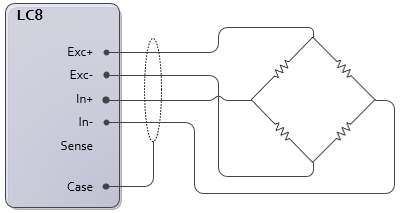
4-Wire Load Cells
Connect 4-wire load cells as follows:
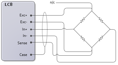
6-Wire Load Cells
Connect 6-wire load cells as follows. To use the continuous wire sense feature, the Exc+ and Exc- wires must be of the same length and gauge. This is because the RMC assumes that the voltage drop from the supply voltage output (Exc+) to the load cell is identical to the voltage drop from the load cell to Exc-.
Using External Excitation
The LC8 module excitation voltage is 6.75 V. However, an external excitation may be applied to the load cell instead. Therefore, if the 6.75 V excitation will cause the load cell signal to exceed the LC8 voltage input, a lower external excitation may be used to reduce the load cell signal to within the limit of the RMC’s input. Conversely, a higher excitation voltage may be used (up to 10V) to increase the output from the load cell as long as the the Max Differential Input (±34.25 mV) is not exceeded and the input voltage at In+ or In- relative to Exc- is within the Input Voltage Range (0.6 V to 6.15 V typical). This can improve the signal to noise ratio in particularly sensitive applications.
4-Wire Load Cell with External Excitation
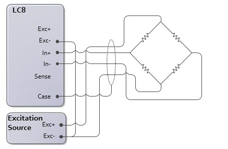
The external Exc- pin must be connected to the LC8 Exc- pin.
6-Wire Load Cell with External Excitation
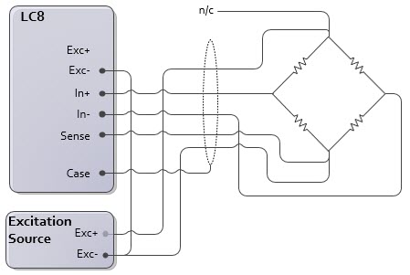
The external Exc- pin must be connected to the LC8 Exc- pin.
Strain Gauges
Wiring strain gauges to the LC8 module requires a bridge completion circuit. The individual resistances of the Wheatstone bridge completion circuit must be matched to the strain gauge resistance. Common resistance values are 120 or 350 Ohms. Commercially available bridge completion modules typically offer an adjustment to zero the bridge output. See the Third Party Recommendations section of Delta's forum for commercially available bridge completion modules.
A single load strain gauge requires three resistors to complete the bridge. The strain gauge may be placed in any location of the bridge. This is called a quarter bridge:
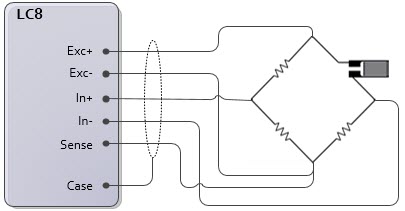
The Sense wire may be omitted if the Adaptive Exctier Mode is not used.
Two strain gauges require two resistors to complete the bridge. This is called a half bridge. The strain gauges form one side of the bridge, and the completion circuit forms the other side:
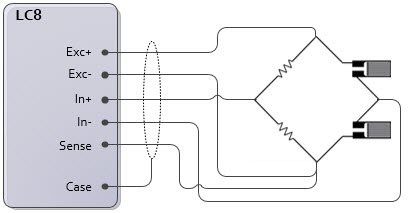
The Sense wire may be omitted if the Adaptive Exciter Mode is not used.
See Also
Wiring Guidelines | LC8 Module | Load Cell Fundamentals
Copyright © 2026 Delta Computer Systems, Inc. dba Delta Motion