The RMC200 LC8 module supports load cells made of strain gauges in a Wheatstone bridge configuration. This topic briefly describes these concepts. More complete information is readily found from other sources.
Strain Gauge
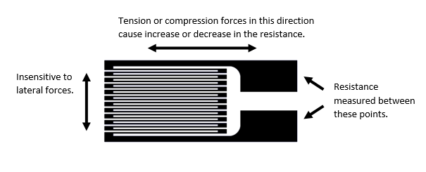
A strain gauge is an electrical sensor that measures strain (deformation of a material) caused by stress (force on a material). It consists of a resistive element, such as a wire, bonded to or printed on the surface of a material. As the material stretches or compresses, the length and cross-sectional area of the resistive element change, resulting in a change in resistance. This change in resistance can be used to determine the change in force.
The change in resistance is typically very small and can be difficult to measure. A long wire improves the measurability. To fit a long wire into a small area, the wire is bent in a zigzag pattern with long parallel lines in the direction of the strain to be measured.
Wheatstone Bridge
A typical method of accurately measuring a small change in resistance is to use a Wheatstone bridge. Wheatstone bridges are used in many applications, including measuring strain. The bridge circuit consists of two voltage dividers wired in parallel, with a common voltage source:
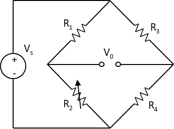
The supply voltage VS is a constant dc voltage. The output voltage is measured at V0. If all the resistances are equal, V0 is zero, and the circuit is said to be balanced. If one resistance, such as R2, changes, V0 will change.
Load Cell
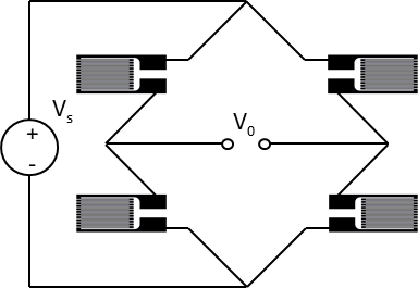
A load cell consists of strain gauges in a Wheatstone configuration, bonded to elements that are designed to bend as a load is applied. There are many possible permutations of the number of strain gauges, their orientations, the geometry of the load cell, and the strain gauge locations in the load cell.
A load cell with four strain gauges is the most common and is called a full bridge:
Load Cell Output Signal
The change in V0 is typically very small, on the order of millivolts. The voltage change is also proportional to the supply voltage, VS. Therefore, the output V0 of a load cell made of a Wheatstone bridge is specified as the number of millivolts per volt of supply voltage at the rated load of the load cell.
For example, a load cell output may be specified as 2 mV/V. That means for a supply voltage of 6.75 V, the output of the load cell at its maximum rated load will be 2 mV x 6.75 V = 13.5 mV. If the load cell is compression only or tension only, as the load changes, the output of the load cell will vary between 0 and 13.5 mV, proportional to the load. If the load cell works in both compression and tension, as the load changes, the output of the load cell will vary between -13.5 mV and 13.5 mV, proportional to the load.
Typically, any load cell that has an output specified in mV/V is compatible with the RMC’s load cell inputs, as long as the maximum output voltage V0 is less than the RMC’s maximum input rating.
The LC8 module excitation voltage is 6.75 V. However, an external excitation may be applied to the load cell instead. Therefore, if the 6.75 V excitation will cause the load cell signal to exceed the LC8 input specification, a lower external excitation may be used to reduce the load cell signal to within the limit of the RMC’s voltage input. Conversely, a higher excitation voltage may be used (up to 10V) to increase the output from the load cell as long as the maximum voltage output of the load cell does not exceed the input limit. This can improve signal to noise ratio in particularly sensitive applications.
Wire Sense for Load Cells
Achieving accurate measurements from a load cell requires knowing the precise voltage that is being applied to the load cell. The controller supplies a fixed DC voltage. The resistance in the supply and return wires will reduce that voltage by an amount dependent on the wire length and gauge. This effect can be significant for long wire runs. Therefore, many load cells add two remote sensing wires so the controller can measure the voltage that is actually being applied at the load cell and use that voltage in the calculation of the mV/V signal. This provides a more accurate measurement.

Wire Sense in the LC8 Module
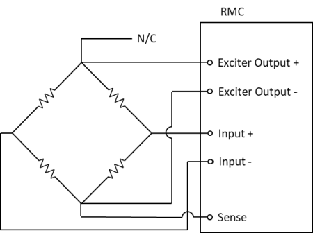
To measure the supply voltage at the load cell, the LC8 module offers a single Wire Sense input. This measures the voltage of the Sense- wire relative to the zero reference of the excitation voltage (Exc-). The RMC assumes that the voltage drop from the supply voltage output (Exc+) to the load cell is identical to the voltage drop from the load cell to Exc-. Therefore, the Exc+ and Exc- wires must be of the same length and gauge to use the Wire Sense feature.
With the LC8 module, one of the sense wires in 6-wire load cells will be unused:
Using Individual Strain Gauges
Instead of using a complete load cell with a full Wheatstone bridge, some applications may use a single strain gauge or two strain gauges. In these cases, a bridge completion circuit must be used to provide a complete Wheatstone bridge for the RMC’s load cell input. The individual resistances of the Wheatstone bridge must be matched to the strain gauge resistance. Common resistance values are 120 or 350 Ohms. Commercially available bridge completion modules typically offer an adjustment to zero the bridge output. See the Third Party Recommendations section of Delta's forum for commercially available bridge completion modules.
A single load strain gauge requires three resistors to complete the bridge. This is called a quarter bridge:
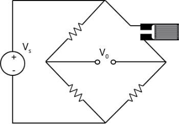
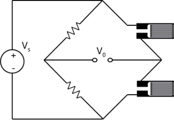
Two strain gauges require two resistors to complete the bridge. This is called a half bridge:
See Also
Feedback Resolution | Wiring Guidelines | LC8 Wiring | LC8 Module (RMC200) | Load Cell Scaling
Copyright © 2026 Delta Computer Systems, Inc. dba Delta Motion