This topic covers the wiring of the RMC200 CV8 Module. The CV8 has 8 voltage outputs and also has 8 discrete I/O that can be individually configured as general-purpose inputs, general-purpose outputs, Fault Inputs, or Enable Outputs.
See Wiring Guidelines for general wiring information.
Pin-Out
Terminal Block 1 (top)
|
Description |
|
Pin |
|
Description |
|
|
Voltage output 0 |
CtrlOut0 |
1 |
2 |
CtrlOut1 |
Output 1 |
|
Output common |
Cmn |
3 |
4 |
Cmn |
|
|
Output common |
Cmn |
5 |
6 |
Cmn |
|
|
Connection to case |
Case |
7 |
8 |
Case |
|
|
Output 2 |
CtrlOut2 |
9 |
10 |
CtrlOut3 |
Output 3 |
|
Cmn |
11 |
12 |
Cmn |
||
|
Cmn |
13 |
14 |
Cmn |
||
|
Case |
15 |
16 |
Case |
||
|
Discrete I/O 0+ |
D0+ |
17 |
18 |
D1+ |
Discrete I/O 1 |
|
Discrete I/O 0- |
D0- |
19 |
20 |
D1- |
|
|
Discrete I/O 2 |
D2+ |
21 |
22 |
D3+ |
Discrete I/O 3 |
|
D2- |
23 |
24 |
D3- |
||
All the Cmn pins in Terminal Blocks 1 and 2 are internally connected.
Terminal Block 2 (bottom)
|
Description |
|
Pin |
|
Description |
|
|
Output 4 |
CtrlOut4 |
1 |
2 |
CtrlOut5 |
Output 5 |
|
Cmn |
3 |
4 |
Cmn |
||
|
Cmn |
5 |
6 |
Cmn |
||
|
Case |
7 |
8 |
Case |
||
|
Output 6 |
CtrlOut6 |
9 |
10 |
CtrlOut7 |
Output 7 |
|
Cmn |
11 |
12 |
Cmn |
||
|
Cmn |
13 |
14 |
Cmn |
||
|
Case |
15 |
16 |
Case |
||
|
Discrete I/O 4 |
D4+ |
17 |
18 |
D5+ |
Discrete I/O 5 |
|
D4- |
19 |
20 |
D5- |
||
|
Discrete I/O 6 |
D6+ |
21 |
22 |
D7+ |
Discrete I/O 7 |
|
D6- |
23 |
24 |
D7- |
||
All the Cmn pins in Terminal Blocks 1 and 2 are internally connected.
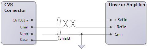
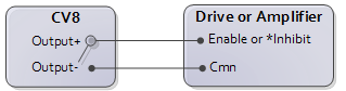
Wiring to Differential Inputs
Differential inputs provide the best noise immunity. This is indicated by individual +, -, and cmn inputs on the drive or amplifier.
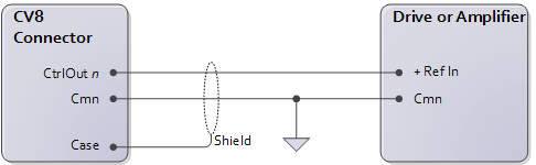
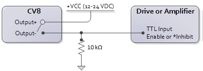
Wiring to Single-ended Inputs
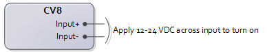
Discrete Input Wiring
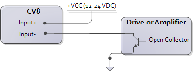
Each discrete input is compatible with signal levels ranging from 12V to 24V. The discrete input draws 3mA maximum and turns on at 9V. The discrete input turns on when a current flows. The polarity of the voltage is unimportant. See the Fault Input topic for details on using this input as a Fault Input.
|
Generic:
|
From Open Collector Output:
|
Discrete Output Wiring
Each discrete output is a solid state relay (SSR). When it is off, it has high impedance, and when on it has low impedance (12 Ω maximum). Because the discrete output is isolated, the user must power it externally. The maximum current and voltage for the discrete output is 75 mA and 30 V.
The discrete output has a + and - connection. Both lines must be connected for the output to function. Because both sides of the output are provided, the switches may be independently connected in a high side or low side configuration (that is, with the load (input) on the source or sinking side of the output).
See the Enable Output topic for details on using this output as an Enable Output.
To active low Enable input:
To TTL input (high = enable):
Using Outputs with Inductive Loads
External fuses should be used to protect the SSRs if there is a possibility of over-current. When switching inductive loads, it is important to place a diode or tranzorb across the load to protect the switch when transitioning from an “ON” to an “OFF” state. Otherwise, the collapsing magnetic field can cause a reverse voltage spike in excess of the 30 V rating of the SSR.
See Also
Copyright © 2026 Delta Computer Systems, Inc. dba Delta Motion