This topic covers the wiring of the Resolver inputs on the RMC150 Resolver (R) and Resolver (RW) modules. For the Control Output (Drive) wiring, see the RMC150 Control Output (Drive) Wiring topic.
Use shielded twisted pairs for all connections to inputs and outputs. Route the transducer wiring separate from other wiring. See Wiring Guidelines for general wiring information.
Wire clamp screws must be tightened to max 4.5 lb-in (0.51 Nm).
Pin-Out
|
Resolver (R) Input 0
Resolver (R) Input 1
|
Resolver (RW) Input 0
Resolver (RW) Input 1
|
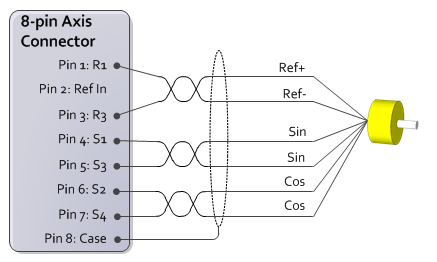
Typical Wiring Diagram
Resolver (R) Module
Below is a typical wiring diagram for resolvers that fall within the Resolver (R) module's reference signal specifications (800Hz to 5kHz and 1.42 to 4.8V RMS). The Ref In input is only used for reference signals outside of these specifications, and requires contacting Delta for assistance.
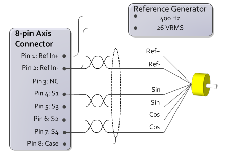
Resolver (RW) Module
Below is a typical wiring diagram for the Resolver (RW) module.
See Also
Resolver (R) Module (RMC150) | RMC150 Control Output (Drive) Wiring | Wiring Guidelines
Copyright © 2026 Delta Computer Systems, Inc. dba Delta Motion