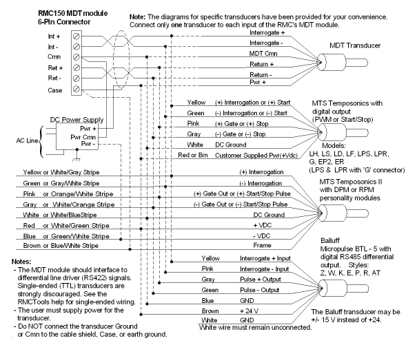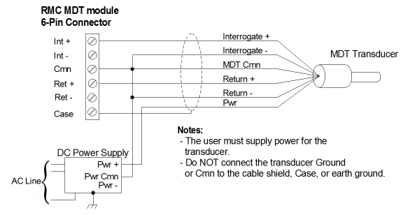
This topic covers the wiring of the Start/Stop and PWM inputs on the RMC150 MDT (M) module. For the Control Output (Drive) wiring, see the RMC150 Control Output (Drive) Wiring topic.
Use shielded twisted pairs for all connections to inputs and outputs. Route the transducer wiring separate from other wiring. You must provide the power supplies needed by your transducers. See Wiring Guidelines for general wiring information.
Wire clamp screws must be tightened to max 4.5 lb-in (0.51 Nm).
The commons are internally connected.
Note:
The MDT input Cmn pin must be connected!
A disconnected Cmn pin can
cause noise and inaccurate readings.
Start/Stop and PWM Transducers with Differential Line Driver (RS422) Signals

Start/Stop and PWM Transducers with Single-Ended Signals
This diagram applies to older transducers, such as the Temposonics I and II transducers with neuter outputs. Single-ended transducers are not recommended due to poor noise immunity.

See Also
MDT (M) Module (RMC150) | RMC150 Control Output (Drive) Wiring
Copyright © 2025 Delta Computer Systems, Inc. dba Delta Motion