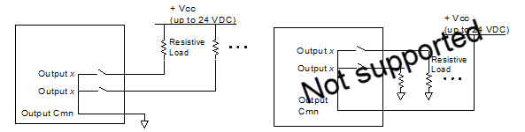
Figure 1: SSR switching resistive load: low-side configuration.
Figure 2: High-side configuration not supported.
This topic covers the wiring of the discrete inputs and outputs on the RMC150 DI/O module (DI/O or D). For wiring the discrete I/O on the RMC150E CPU, see the RMC150E Wiring. For wiring the UI/O module, see the RMC150 UI/O Wiring. See Wiring Guidelines for general wiring information.
Wire clamp screws must be tightened to max 2.2 lb-in (0.25 Nm).
DI/O Module Outputs
The DI/O module outputs are solid state relays. When they are ”off” they have high impedance, and when ”on” they have low impedance (50Ω maximum, 25Ω typical). The user must power the outputs externally. The maximum current and voltage for the outputs is 75 mA (50 mA for Class I, Div 2) and 30 V.
Outputs can be wired in either a low-side configuration only.
Using Outputs with Resistive Loads
|
|
|
|
Figure 1: SSR switching resistive load: low-side configuration. |
Figure 2: High-side configuration not supported. |
The load resistance must be sized such that the maximum current through the SSR does not exceed 50mA. The maximum current is calculated with the following equation:
Current = Vcc / RLoad
For example, if the supply voltage Vcc is 24V, and the load resistance is 480Ω, the current will be:
Current = 24Ω / 480Ω = 50mA
which is right at the 50mA limit. The load resistance should not be decreased any further with a 24V supply voltage.
Using Outputs with Inductive Loads
External fuses should be used to protect the SSRs if there is a possibility of over-current. When switching inductive loads, it is important to place a diode or tranzorb across the load to protect the switch when transitioning from an ”ON” to an ”OFF” state. Otherwise, the collapsing magnetic field can cause a reverse voltage spike in excess of the 30 V rating of the SSR. See figures below for details.
Figure 3: SSR switching inductive inductive load: high-side configuration.
![]() Example: Calculating maximum current
for inductive load.
Example: Calculating maximum current
for inductive load.
DI/O Module Inputs
The DI/O module inputs consist of a single common and eighteen individual input connections and are compatible with signal levels ranging from 5V to 24V. Each input draws a maximum of 10mA with a 24V input. Most P/C outputs can be connected to the DI/O inputs directly. The exception is open collector (sinking) outputs. See the discussion below for using open collector outputs.
Note:
The numbered inputs must be positive relative to the Input
Cmn pin. That is, these are sinking inputs.
The following are some input wiring diagrams:
|
|
|
Figure 4: Direct connection to Programmable Controller. |
|
|
|
Figure 5: Direct connection to Programmable Controller. |
Using DI/O Module Inputs with Open Collector Outputs
The DI/O module inputs can be used with open collector (sinking) outputs. There are two configurations that can be used to drive the discrete inputs from an open-collector output:
Figure 6: PNP Configuration: This configuration is the most popular for open collector PNP outputs.
Figure 7: Open Collector Outputs to the DI/O Module Inputs with Input Common Connected to Ground.
For 24VDC power, the pull-up resistor should be a 3.3 kΩ, 1/2 watt resister. The output must be capable of switching 7.5mA when closed. When the open collector output is open, the DI/O input sees 7V @ 5.1mA.
For 12VDC power, the pull-up resistor should be a 560 Ω, 1/8 watt resister. The output must be capable of switching 9.0mA when closed. When the open collector output is open, the DI/O input sees 3.1V @ 3.4mA.
Dividing the Input Voltage
Because the DI/O module inputs are designed for use with 5V outputs, the threshold is 2.75VDC. This is a small percentage of the 24V outputs. As a result, it is important that the inputs have very little noise. This section describes using a voltage divider to raise the apparent input threshold.
Note: Before resorting to dividing the input voltage, take all possible measures to eliminate noise from the inputs.
To divide the inputs, attach resisters to each input as shown in the following diagram:
This configuration will reduce noise susceptibility by a factor of about five.
See Also
Copyright © 2026 Delta Computer Systems, Inc. dba Delta Motion