The RMC200 supports synchronization of its loop time with a precise external signal, such as a Pulse Per Second signal.
Loop time synchronization may be used for applications such as:
Synchronize the RMC’s data with an external data acquisition system
Synchronize the RMC’s control with an external device
Synchronize the loop times of multiple RMCs.
Basics
Synchronizing the loop time involves the following:
High-Speed Input with Event Timer
The external signal must be wired to a high-speed input on the RMC that supports Event Timers. The Event Timer must be configured to continuously record the time at which the signal pulse occurs.
User Program to Continuously Calculate Loop Time Adjustment
Write a user program that continuously:
Records the time within the loop time at which the signal pulse occurs.
Calculates how much to adjust the loop time to keep it synched with the external signal. This calculation is similar to a control algorithm and uses a proportional and integral calculation.
Writes to the Loop Time Adjust register to adjust the loop time.
Supported RMC Inputs
Only inputs that support Event Timers may be used for Loop Time Synchronization:
D24 module: High-speed inputs 20-23. These may be configured either as discrete inputs or as quadrature inputs.
Control Output Timing
In systems where the RMC’s analog control output timing and jitter is important, loop time synchronization may optionally be used with Control Output Timing, which posts the analog outputs to the Digital-to-Analog Converter (DAC) at a fixed time (end of loop) each loop time rather than posting the outputs to the DAC as soon as the motion loop finishes calculating them. This reduces the output jitter. See the Control Output Timing axis parameter for details.
Using Event Timers with Loop Time Synchronization
An Event Timer will capture the time within a loop time that a rising or falling edge of a signal occurs, in nanoseconds.
Use the Arm Event Timer (105) command to start the event timing. Specify the I/O module slot that will be used, which Event Timer, the source (rising or falling edge or quadrature count), and set the Timer Mode to Continuous. For more details, see the Arm Event Timer (105) command.
The Event Timer has an Event Timer Latched bit that will turn on in the loop time that the specified event occurred. In continuous mode, it will turn off the next loop time and stay off until the event occurs again. This status bit can be monitored in a user program to tell the user program to process that data. For details on the status bit address, see Event Timers.
The time an event occurred is stored as seconds and nanoseconds. The nanoseconds go from 0 to 999,999,999 each second. To determine the time difference between the nearest loop tick (beginning of a loop time) and the event time, only the nanoseconds need to be used.
You may wish to synchronize the beginning of the RMC loop time to the external signal, or you may wish to have an offset (LoopTickOffset).
You may need to subtract one loop time to get the time difference from the nearest loop tick. For details on the nanoseconds register address, see Event Timers.
Use the following formula for this:
Time_to_nearest_loop_tick = (Event_time_nanoseconds + LoopTickOffset) MOD Loop_time_nanoseconds;
IF Time_to_nearest_loop_tick > Loop_time / 2 THEN
Time_to_nearest_loop_tick = Time_to_nearest_loop_tick – Loop_time;
END IF
The nanoseconds are moduloed by the loop time to determine the time difference between the event and the nearest loop tick. The loop time is subtracted to get the correct time difference from the beginning of the loop tick. For details on the nanoseconds register address, see Event Timers.
Calculating the Loop Time Adjustment
When the synchronization first starts, you may wish to adjust the controller’s loop time quickly to match the signal. In this case, simply use the time difference between the event and the nearest loop tick, and apply that difference for one second. Because the maximum loop time adjustment allowed is 8 microseconds per millisecond, the entire initial time difference cannot be adjusted in a single loop time. During this one second where the large change is applied, the controller should not be controlling axis movement because some types of feedback may be disrupted.
Once the first large synchronization adjustment has been made, small adjustments must be made to continuously keep the loop time synchronized. This can be done by multiplying the time difference by some factor (a proportional gain). For better performance, also keep track of the accumulated error and multiply that by some factor (an integral gain). These gains must be adjusted for optimal performance. The combination of these gains will keep the loop time tightly synched.
Example: PPS Synchronization
Consider an RMC200 that synchronizes to a PPS signal. This signal is wired to a D24 module in slot 14, input 20.
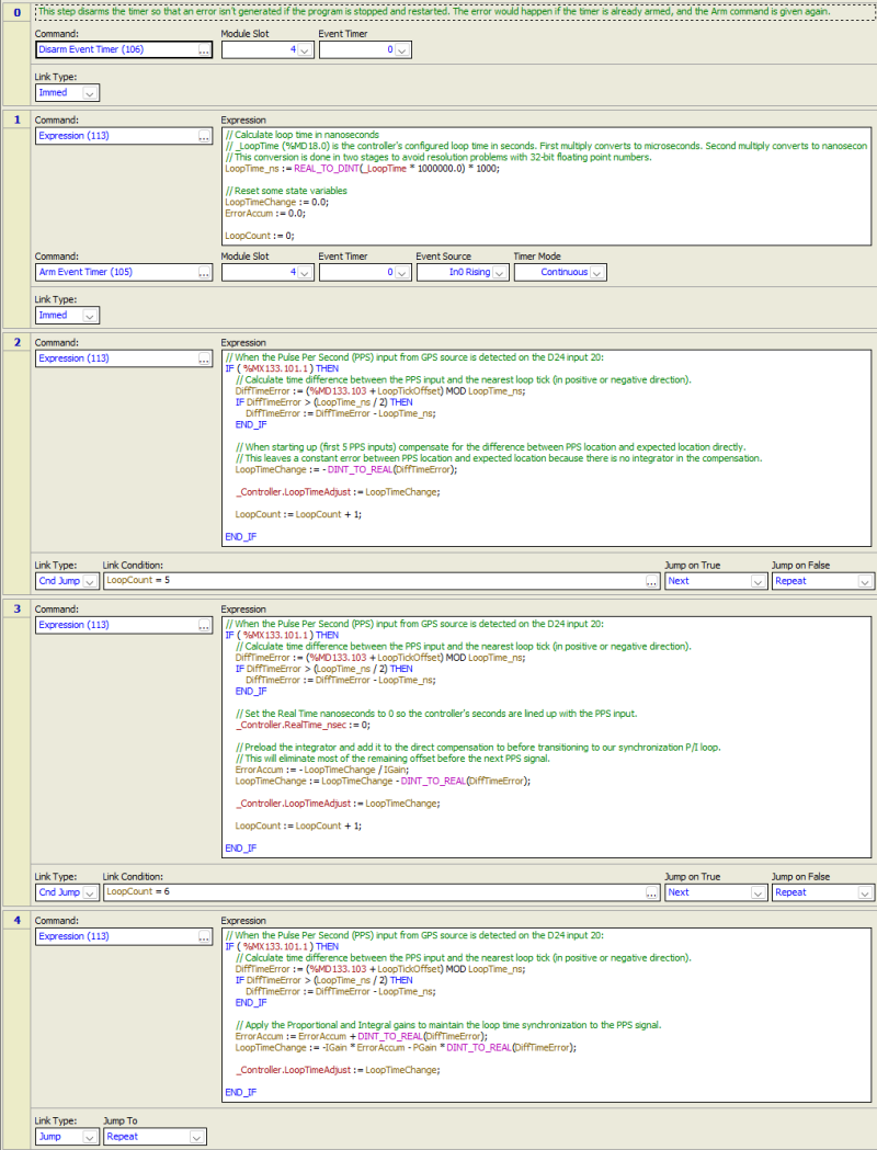
The example user program and its variables are shown below. It consists of 3 sections:
Arms the Event Timer and initializes variables (steps 0 and 1).
Rapid adjustment of loop time to match input signal (steps 2 and 3).
Continuously calculates the time difference and determines how much to adjust the loop time to keep it synchronized (step 4).
Note: This user program is available on Delta Motion’s forum: forum.deltamotion.com. Search for ‘loop time synchronization’.
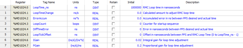
Variables:
User Program:
See Also
Loop Time Adjust Register | Control Output Timing
Copyright © 2026 Delta Computer Systems, Inc. dba Delta Motion