
Event Timers are used to capture the precise time at which an external event occurs, such as a high-speed discrete input turning on or off, or a quadrature count changing. The time of an event will be latched at a much finer resolution than the Loop Time time of the controller. The captured time is stored in two 32-bit registers using the standard format for the system time (seconds & nanoseconds since the start of the first motion control loop). The RMC system time is monotonically increasing and will never be adjusted when the real time is changed, so times captures can simply be subtracted from one another.
Event Timers can be used for timing-related applications such as:
Calculating the time between pulses on a single input.
Calculating the time between two different inputs turning on.
Calculate a pulse width.
See the Applications section below for instructions on how to perform specific Event Timer applications.
Supported Modules
|
Module |
# of Event Timers |
Time Resolution |
|
4 |
Measurement resolution: 25 ns See the D24 topic for propogation delay specifications. |
Capturing the Time of an Event
Determine slot number
Determine the slot number of the module with the high-speed input.
|
Base |
Slot Numbers |
|
B5 |
2–4 |
|
B7 |
2–6 |
|
B11 |
2–10 |
|
B15 |
2–14 |
Choose an Event Timer and Event Source
The Event Timer is the internal software resource for the timer, not the actual hardware input. The Event Timers serve to keep track of the physical timing events. The number of simultaneous events that can be timed on a module is limited by the number of Event Timers available for the module.
|
Module |
Event Timers |
|
D24 |
0–3 |
The Event Source is the physical event that will be timed. This can be a quadrature count change, or a discrete input change. Certain Event Timers are supported for certain Event Sources.
D24 Hardware Inputs:
|
Event Timers |
Event Source Names |
Hardware Input |
|
0 or 1 |
Quad Count: Any change in the quadrature count, useful for calculating velocity from last two counts. |
Quadrature Channel 0 |
|
In0 Rising Edge, In0 Falling Edge |
Discrete Input D20 |
|
|
In1 Rising Edge, In1 Falling Edge |
Discrete Input D21 |
|
|
2 or 3 |
Quad Count: Any change in the quadrature count, useful for calculating velocity from last two counts. |
Quadrature Channel 1 |
|
In0 Rising Edge, In0 Falling Edge |
Discrete Input D22 |
|
|
In1 Rising Edge, In1 Falling Edge |
Discrete Input D23 |
Choose Timer Mode
The following modes are available. See the Applications section below for more details.
One-Shot
The Event Timer will capture the time of the first occurrence of the event after the timer is armed. This is useful when multiple pulses may occur, but only the time of the first one is desired.
Continuous
The Event Timer will continue to capture the time of each occurrence of the event after the timer is armed. The time of the most recent event will be stored in the Event Timer registers. This is useful when multiple events may occur within a single loop time, and the time of the last event is desired. To stop capturing, use the Disarm Event Timer (106) command.
Alternating
The Event Timer will capture the time of every other occurrence of the event after the timer is armed. To use the Alternating mode, two Arm Event Timer commands must be used on two separate Event Timers, with both Event Timers using the same module slot, event source, and timer mode (Alternating), and the two Event Timers must be in the same pair. On the D24, 0 and 1 are a pair, and 2 and 3 are a pair.
Once Alternating mode has been armed, the first event timer will latch on the first occurrence of the event, then the second event timer will latch on the next occurrence, then the first event timer will latch on the next occurrence, and the event timers will continue to alternate in this fashion.
To stop capturing, use the Disarm Event Timer (106) command.
Alternating mode is useful for measuring the time between the last two counts from the quadrature encoder, which can then be used to calculate speed.
Send Command
Send the Arm Event Timer (105) command. The commanded axis is irrelevant. This will arm the specified Event Timer, and the Event Timer Armed status bit will be set. See the Event Timer Status Bits section below for more details.
Wait for Event
Once the event has occurred, the Event Timer Latched bit will be set. See the Event Timer Status Bits section below for more details. For the Continuous and Alternating timer modes, use the Disarm Event Timer (106) command to disarm the timer when done.
View the Latched Time
The latched time will be stored in the following registers, as described in the Event Timer Registers section below.
Event Timer n Seconds
Event Timer n Nanoseconds
Calculate Time Differences
Typically, any timing application will involve calculating the time between events. See the Event Timer Calculations section below for details on how to calculate the time differences.
Event Timer Status Bits
Each Event Timer has an Event Timer Armed status bit and an Event Timer Latched status bit:
Event Timer Armed status bit
The Event Timer Armed status bit will be set when the Event Timer is armed. For the One-Shot timer mode, once the Event Timer latches, the Armed bit will be cleared. For the Continuous and Alternating timer modes, the Armed bit will remain set until the Disarm Event Timer (106) command is sent to disable the Event Timer.
Event Timer Latched status bit
If the Event Timer is armed, the Event Timer Latched status bit will be set once the event occurs. In One-Shot mode, the Latched bit will remain set until the Event Timer is re-armed or disabled. In Continuous or Alternating mode, the Latched bit will be set only for the loop when the event time is latched, and then cleared on the next loop.
|
Name |
Tag Name |
Data Type |
Address |
|
Event Timer Armed |
none |
Boolean |
%MDs.b.0 s= 129 + slot number b = 101 + 4 x Event Timer Number |
|
Event Timer Latched |
none |
Boolean |
%MDs.b.1 s= 129 + slot number b = 101 + 4 x Event Timer Number |
Event Timer Registers
The time of an event is recorded in the Event Timer Seconds and Event Timer Nanoseconds registers. The Event Timer Seconds register holds the number of whole seconds, and the Event Timer Nanoseconds register holds the remaining number of nanoseconds.
Each Event Timer has one dedicated Event Timer Seconds register and one dedicated Event Timer Nanoseconds register. The time uses the standard epoch for the RMC system time (seconds & nanoseconds since the start of the first motion loop). Notice that the Event Timer Seconds and Nanoseconds registers share the same time base as the Time, Seconds and Time, Nanoseconds registers described in the System Time topic.
|
Name |
Tag Name |
Data Type |
Address |
|
Event Timer Seconds |
none |
DINT |
%MDs.b s= 129 + slot number b = 102 + 4 x Event Timer Number |
|
Event Timer Nanoseconds |
none |
DINT |
%MDs.b s= 129 + slot number b = 103 + 4 x Event Timer Number |
Event Timer Calculations
Event times are stored as Seconds and Nanoseconds registers that together represent a time. These two registers share the same time base. For example, a time of 13.568 seconds would be represented by a value of 13 in the Seconds register, and 568,000,000 in the Nanoseconds register.
To calculate the time between two events:
Determine the register addresses of the Event Timer Seconds and Event Timer Nanoseconds registers for each of the two events. This is described in the Event Timer Registers section above.
Check the Event Timer Latched status bits to ensure the timer values have latched. This is described in the Event Timer Status Bits section above.
Calculate the time difference of the two events.
Use one of the TIME_DIFF functions provided by Delta, as described in the Time User Functions section below. The function will take the Event Timer Seconds and Event Timer Nanoseconds registers for each of the two events.
If necessary, convert the time difference to a REAL data type in the desired units of seconds, milliseconds, or nanoseconds.
The function used to compute the time difference may perform this conversion. Otherwise, use one of the provided functions to perform the conversion.
Time User Functions
Delta has provided several user functions as described in the System Time topic to calculate the difference between two times, and to convert to a REAL value in seconds or milliseconds. The functions can be obtained from Delta's forum at https://forum.deltamotion.com/. Search for Time Functions, download the User Function Library (.rmcflib) file, and import it into the User Functions in RMCTools.
Applications
Following are instructions for measuring times for specific applications.
The functions in this example can be obtained from Delta's forum at https://forum.deltamotion.com/. Search for Time Functions, download the User Function Library (.rmcflib) file, and import it into the User Functions in RMCTools.
Time Between Pulses on a Single Input
Follow these steps to measure the time between two pulses on a single input. This will capture the two last events prior to measurement. For example, if the inputs alternated 10 times in a loop time after arming, step 1 of the user program would perform calculations on the last two input events.
Arm two different timers in alternating mode. The Event Source will be identical for both timers, for example In0 Rising Edge.
Wait for the timers to latch.
Calculate the time difference.
Example user program:
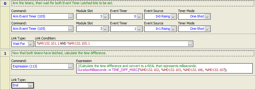
Time Between Pulses on Two Different Inputs
Follow these steps to measure the time between a pulse on one input, and a pulse on another input. This will capture the first pulse on each input after the Event Timer is armed.
Arm two different timers in one-shot mode. Choose the two inputs you wish to use for the Event Sources. Typically, both timers will be the rising edge, but your specific application may differ depending on the edge you wish to measure.
Wait for the timers to latch.
Calculate the time difference.
Example user program:
Measure Pulse Duration (Pulse Width)
Follow these steps to measure the width of a pulse. This will capture the first pulse on each input after the Event Timer is armed.
Arm two different timers in one-shot mode. The Event Sources will be the rising edge and falling edge of the same input.
Wait for the timers to latch.
Calculate the time difference.
Example user program:

See Also
Arm Event Timer (105) | Disarm Event Timer (106) | System Time Registers | System Time
Copyright © 2026 Delta Computer Systems, Inc. dba Delta Motion