This topic describes and provides examples of how to use rotary motion with the RMC series motion controller. For a description of rotary axes, see the Axis Type: Rotary/Linear topic.
In general, to move rotary axes, use the same motion commands as you would for linear axes. When positions wrap on the axis, the RMC automatically accounts for it when calculating target profiles, Position Error, etc.
When Should Rotary be Used?
If your machine has a rotary encoder, it does not necessarily mean the axis should be defined as rotary. The application determines whether the axis should be defined as rotary.
Typically, rotary applications are applications where the machine (motor, belt, etc.) rotates through a position cycle and does not have endpoints of travel. That is, it is possible for it continuously travel in one direction without needing to move the opposite direction (it doesn't have to continuously travel in one direction, but it should be possible). Typically, single-turn or multi-turn absolute encoders or incremental encoders are used in rotary applications.
The Positive Travel Limit and Negative Travel Limit do not apply for rotary axes. If you need positive and negative travel limits and you are using a rotary encoder, you should set up the axis as linear.
Rotary Configuration Basics
For rotary axes, the counts per revolution must be a power of two, such as 1024, 8192, etc. This typically means the encoder counter per turn must be a power of two.
The Position Unwind parameter defines the position range the axis will work in. The Position Unwind parameter can be any positive non-zero value. It works together with the Count Unwind and Position Offset parameters to scale the counts to position units.
For more details, see the Rotary Scaling topic.
Example 1:
Assume you have a 10 ft (120 in) long belt and an encoder. You wish to scale the axis for inches. You would set the Position Unwind to 120. As the belt travels, the positions will go from 0 up to, but not including, 120 in. The Count Unwind should be set to the number of counts generated in 120 inches of travel.
Example 2:
Assume you have a motor with an encoder with 8000 counts per turn, and the encoder turns 4 times per machine revolution. You wish to scale the axis for degrees. You would set the Position Unwind to 360 and the Count Unwind to 32000 (8000 x 4). As the motor turns, the positions will go from 0 up to, but not including, 360 degrees.
Rotary Motion Command Behavior
The sections below describe how commands behave on rotary axes:
Rotary Motion with Absolute Position Moves
This section applies to the following commands:
Each of the commands listed above has a Direction parameter with the following options for rotary axes:
The axis will move to the Requested Position in the direction of increasing position units. If the Command Position is less than the current Target Position, the axis will wrap around to the Requested Position. If the Requested Position command parameter is outside the valid range of the axis, the Command Position will be set within the valid range using modular arithmetic such that the position will be the same location within the range. For example, if the valid range is 0-360 (not including 360), and the Requested Position is 800, the Command Position will be set to 80 (800 mod 360). Likewise, with a Requested Position of -100, the Command Position will be set to 260 (360 + (-100 mod 360)). The Command Position will never be more than 1 revolution from the current Target Position.
Example:
Consider a rotary axis with a Position Unwind of 360 and a current Target Position of 180. A move to 90 with the Positive Direction parameter will cause the axis to pass 0 (wrap), and end at 90 position units.
The axis will move to the Requested Position in the direction of decreasing position units. If the Command Position is greater than the current Target Position, the axis will wrap around to the Requested Position. If the Requested Position command parameter is outside the valid range of the axis, the Command Position will be set within the valid range using modulo arithmetic such that the position will be the same location within the range. For example, if the valid range is 0-360 (not including 360), and the Requested Position is 800, the Command Position will be set to 80 (800 mod 360). Likewise, with a Requested Position of -100, the Command Position will be set to 260 (360 + (-100 mod 360)). The Command Position will never be more than 1 revolution from the current Target Position.
Example:
Consider a rotary axis with a Position Unwind of 360 and a current Target Position of 180. A move to 270 with the Negative Direction parameter will cause the axis to pass 0 and end at 90 position units.
The axis will move to the Requested Position in the direction that results in the shortest distance of travel. If the Requested Position command parameter is outside the valid range of the axis, the Command Position will be set within the valid range using modulo arithmetic such that the position will be the same location within the range. For example, if the valid range is 0-360 (not including 360), and the Requested Position is 800, the Command Position will be set to 80 (800 mod 360). Likewise, with a Requested Position of -100, the Command Position will be set to 260 (360 + (-100 mod 360)). The Command Position will never be more than 1 revolution from the current Target Position.
Example:
Consider a rotary axis with a Position Unwind of 360 and a current Target Position of 180. A move to 270 with the Nearest Direction parameter will cause the axis to go directly to 270. Likewise, with a current Target Position of 45, a move to 270 with the Nearest Direction parameter will cause the axis to pass 0 and go to 270.
This option is very useful for moving the axis through multiple revolutions. With the Absolute option, the Move command mimics a linear axis. The Requested Position command parameter can be any value; it does not need to within the valid range of the axis. When the command is issued, the value in the Requested Position command parameter is treated as a position on a linear axis; the axis begins moving toward the position as if on a linear scale. If the position is outside of the valid position range, the axis rotates through the number of revolutions required to reach the position. Each time the Target Position wraps during the move, the Position Unwind value is subtracted from the Command Position until the Command Position is within the valid position range.
Relative point-to-point moves can also be used to move the axis through multiple rotations. See the Rotary Motion with Relative Point-to-Point Moves section below.
Example:
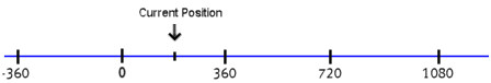
For example, consider a rotary axis with a Position Unwind of 360 where the Actual Position is at 180. When a Move command is issued with the Absolute Direction parameter, the Move command considers the axis as if it were linear, as shown below. Each labeled mark on the axis represents one revolution. Therefore, moving to 720 would move the axis 1.5 revolutions. Notice that when it reaches the final position, the Command Position will be 0, not 720, because it subtracted 360 each time it wrapped.
This option will move to the Requested Position in the current direction. The current direction is determined by current velocity of the axis. If the axis is already in closed-loop control, the Target Velocity is used. If the axis was in open-loop control when the command was issued, then the Actual Velocity will be used. If the axis’s current velocity is zero when the command is issued, it will behave as the Nearest direction parameter option.
If the Requested Position command parameter is outside the valid range of the axis, the Command Position will be set within the valid range using modulo arithmetic such that the position will be the same location within the range. For example, if the valid range is 0-360 (not including 360), and the Requested Position is 800, the Command Position will be set to 80 (800 mod 360). Likewise, with a Requested Position of -100, the Command Position will be set to 260 (360 + (-100 mod 360)). The Command Position will never be more than 1 revolution from the current Target Position.
Rotary Absolute Motion Examples
Example 1: Basic Rotary Move
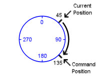
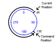
Consider a rotary axis with a single-turn encoder with a Position Unwind value of 360 and a Position Offset of 0. Therefore, the position range extends from 0 up to, but not including, 360. Assume the current position of the axis is 45. You issue a Move Absolute command with a Position command parameter of 135. The following illustrations explain how the axis will behave for each possible Direction parameter:
|
Positive |
Negative |
|
The axis will move in the positive direction to the Command Position, as shown below:
|
The axis will move in the negative direction to the Command Position, as shown below:
|
|
Nearest |
Absolute |
|
The axis will move in the direction that gives the shortest path to the Command Position, as shown below:
|
The axis will move as if it were a linear axis. Therefore, the axis will move to the Command Position in the direction of increasing position units, as shown below:
|
Example 2: Basic Rotary Move
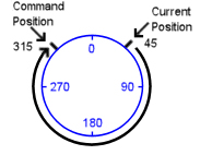
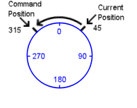
Consider a rotary axis with a single-turn encoder with a Position Unwind value of 360 and a Position Offset of 0. Therefore, the position range extends from 0 up to, but not including, 360. The current position of the axis is 45. You issue a Move Absolute command with a Position command parameter of 315. The following illustrations explain how the axis will behave for each possible Direction parameter:
|
Positive |
Negative |
|
The axis will move in the positive direction to the Command Position, as shown below:
|
The axis will move in the negative direction to the Command Position, as shown below:
|
|
Nearest |
Absolute |
|
The axis will move in the direction that gives the shortest path to the Command Position, as shown below:
|
The axis will move as if it were a linear axis. Therefore, the axis will move to the Command Position in the direction of increasing position units, as shown below:
|
Example 3: Multiple Rotations
This example illustrates how to use the Absolute option in the Direction command parameter to move a rotary axis through multiple revolutions.
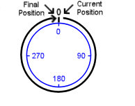
Consider a rotary axis with a single-turn encoder with a Position Unwind value of 360 and a Position Offset of 0. Therefore, the position range extends from 0 up to, but not including, 360. The current position of the axis is 0. You issue a Move Absolute command with the Absolute option in the Direction command parameter. The following illustrations explain how the axis will behave for various values of the Position command parameter:
|
Position command parameter = 360 |
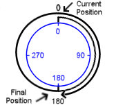
Position command parameter = 540 |
|
The axis will move 1 revolution in the positive direction. The final position will be 0.
|
The axis will move 1.5 revolutions in the positive direction. The final position will be 180.
|
|
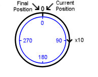
Position command parameter = 3600 |
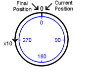
Position command parameter = -3600 |
|
The axis will move 10 revolutions in the positive direction. The final position will be 0.
|
The axis will move 10 revolutions in the negative direction. The final position will be 0.
|
Rotary Motion with Relative Position Moves
This section applies to the following commands:
These commands are useful for moving the axis through multiple rotations.
Each of the above commands has a command parameter called Displacement. Each command works by moving the axis by the requested Displacement relative to the selected value of Command Position, Target Position, or Actual Position. If the Command or Target Position is selected, and the axis is currently in a mode that does not use that Position (such as open loop) it will be relative to the current Actual Position. The sign of the Displacement specifies the direction of movement. The Displacement can be greater then the Position Unwind, which makes these commands useful for moving the axis through multiple rotations. The Command Position is initially set to the current selected relative-to position plus the requested Displacement. Each time the position wraps, the Position Unwind is subtracted from the Command Position until it reaches the final position.
For example, consider an axis with a Position Unwind of 1.0. Therefore, the position range extends from 0 up to, but not including, 1.0. If the current Command Position is at 0.0 and a Move Relative command is issued with a Displacement of 100 relative to the Command Position, the axis will rotate 100 revolutions and end up at 0.0.
Rotary Motion with Velocity and Gear Moves
This section applies to the following commands:
These commands work like on a linear axis, except that the positions will wrap as usual for a rotary axis.
Rotary Motion with Open Loop Commands
This section applies to the following commands:
The Direct Output (9) and Open Loop Rate (10) commands work like on a linear axis, except that the positions will wrap as usual for a rotary axis.
The Open Loop Absolute (11) and Open Loop Relative (12) commands ramp the Control Output from it's current value to the requested Output. This ramping is linear based on distance (not time) from the current Actual Position to the requested Position or requested Displacement command parameters.
For both these commands, the ramping range is calculated in the same manner as the Command Position is calculated for the point-to-point moves described above; for the Open Loop Absolute command, the range of the ramping is determined by the Direction parameter, and for the Open Loop Relative command, the range of the ramping is determined by the sign of the requested Displacement.
Copyright © 2026 Delta Computer Systems, Inc. dba Delta Motion