Siemens offers several CPUs and Communication Processors (CPs) that support PROFINET, including products in the S7-300, S7-400, S7-1200 and S7-1500 lines. The procedures below describe using TIA Portal version 15 with the S7-1200 CPU, but the steps will be similar for other S7-family products and versions of TIA Portal.
The PROFINET IO connection can be configured for both cyclic and acyclic I/O data:
Cyclic I/O data is always exchanged between the PLC and RMC at the specified update time. For example, status information from the RMC, and variables to be written to the RMC would typically be part of the cyclic data. Cyclic I/O data is defined by the Incoming and Outgoing Cyclic I/O Data. The RMC's support the following number of cyclic I/O registers:
|
|
Max Cyclic I/O Registers in each direction |
|
RMC75E |
128 |
|
RMC150E |
256 |
|
RMC200 |
256 |
Some PLCs may be limited to fewer than the full size supported by the RMC controllers.
Acyclic data is sent only when it is needed. For example, if the PLC creates a curve and sends it to the PLC, that data would typically be sent via the acyclic data. Or, if the PLC needs to read a captured plot from the RMC, that is also best done via the acyclic data. Acyclic I/O data is defined by the Data Records. The maximum length is 2048 registers (8192 bytes) for the RMC75 and RMC150 and 4096 registers (16,384 bytes) for the RMC200.
Determine I/O Data Locations in the RMC
PROFINET IO transfers data back and forth between the RMC and PLC at the specified update time. The user must specify which data items in the RMC should be sent and received. Typically, this is data in the Indirect Data Map.
Set up the Indirect Data map so that one part contains all the data coming from the PLC (Incoming Data), and another part contains all the data going to the PLC (Outgoing Data). Make sure the Incoming and Outgoing Data areas in the Indirect Data Map do not overlap.
The Outgoing Data typically includes RMC status items that the PLC always needs to keep track of, such as actual positions and status bits.
The Incoming Data consists of items that the PLC needs to write to in the RMC. This is typically variables and possibly command registers.
Note:
The Incoming and Outgoing Data locations need not be the Indirect Data
Map. However, the Indirect Data Map is usually the best choice. Other
options are the Variable Table and the command area.
Setting Up the RMC for PROFINET
Do the following in RMCTools:
Select PROFINET Protocol Mode (RMC200 Only)
In order to communicate via PROFINET I/O, the RMC200 must be set to PROFINET Mode:
In the Project pane, expand the RMC, and double-click the CPU.
On the Ethernet page, in the Ethernet Protocol Mode section, click PROFINET Mode, then click OK.
The Ethernet Protocol Mode may also be viewed from the CPU20L or CPU40 Display Screen.
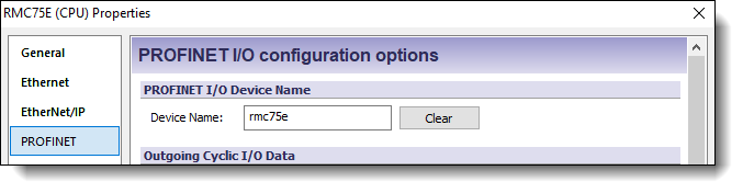
Set the RMC's Device Name
In the Project pane, expand the Modules folder, double-click the CPU module, and choose PROFINET. In the PROFINET I/O DeviceName section, enter the desired unique device name that your IO controller will use to refer to this device:
Set the RMC's IP Address
With PROFINET you can set up the IP address either through RMCTools and instruct the PLC to not change the IP address, or you can allow the IO controller to set the IP address. If you are using Ethernet to connect RMCTools to the controller, then be sure that the IO controller and RMCTools do not conflict on the IP address the module will use.
Set Up the Indirect Data Map
In the Project pane, double-click Address Maps, then click Indirect Data Map.
Beginning at item 0 in the Indirect Data Map, choose the items for the Outgoing Cyclic I/O Data.
At some location in the Indirect Data Map after the Outgoing Cyclic I/O Data area, choose the items for the Incoming Cyclic I/O Data, that is, the items that will be sent to the RMC from the PLC. If you are using another location for your Incoming Data, such as the Variable Table or Command Area, you need not set up the Indirect Data Map for the Incoming Data.
Example
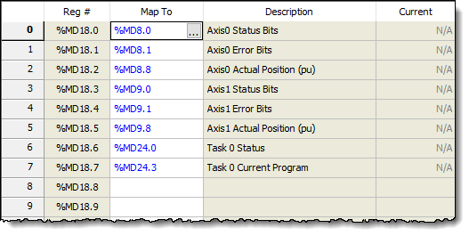
If you have a 2-axis
RMC75E controller, you may wish to set up the Outgoing Data at the beginning
of the Indirect Data Map to include the Actual Position and the Status
Bits for each axis, in addition to information on Task 0, which perhaps
runs your user programs.
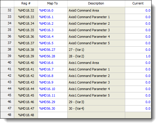
You may also wish to set the Incoming Data, starting at item 32 in the
Indirect Data Map, to go to the Axis 0 and Axis command registers, as
well as some variables. Starting at 32 will simplify expanding the Outgoing
Data later if the application ever requires it.
You could then set up the beginning of the Indirect Data Map like this
for the Outgoing Data:
You could then set up the Outgoing Data further on in the Indirect Data Map like this:
Set the Cyclic I/O Data Locations in the RMC
In the Project pane, expand the Modules folder, double-click the CPU module, and choose PROFINET.
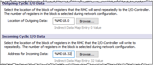
In the Outgoing Cyclic I/O Data section, enter the starting location for the Outgoing Cyclic I/O Data. In our example, verify that the location is the Indirect Data Map Entry 0 Value.
In the Incoming Cyclic I/O Data section, enter the starting address for the Incoming Cyclic I/O Data. Click the Browse button and browse to the desired RMC location for the outgoing data. This should be a location in the Indirect Data Map, the Variable Table, or Command Area as discussed in the Determine I/O Data Locations in the RMC section above.
For example, the PROFINET I/O Configuration Options page below shows an RMC75E with the Outgoing Data coming from the Indirect Data map starting at item 0 and the Incoming Data going to the Indirect Data starting at item 32.
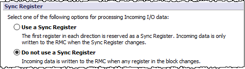
Choose Whether to Use a Sync Register
The Sync Register provides a method for the PLC to synchronize the Input Data and Output Data. With a Sync Register, the Incoming Data is not written to the RMC until the Sync Register changes. If you prefer to have the Incoming Data be written whenever any value in the Incoming Data changes, choose the option to not use a Sync Register.
Because the S7 PLCs use the DPRD_DAT (SFC14) and DPWR_DAT (SFC15) system functions to control when the data is copied into and out of the S7’s DBs, the Sync Register generally does not need to be used with the S7.
To select whether or not to use the Sync Register, in the Project pane, expand the Modules folder, double-click the CPU module, and choose PROFINET. Then select the desired option under Sync Register:
For more details, see the Using a PROFINET I/O Connection topic.
Configure Data Records
While Data Records can be set up at this time, they are not required to establish the PROFINET connection, and are generally better to set up later in the process, once you are planning the acyclic reads and writes the PLC will need to do. See the Using PROFINET Record Data topic for details.
Set the Byte Order
In the Project pane, expand the Modules folder, double-click the CPU module, and choose PROFINET. In the Data Encoding section, make sure the Byte Order is set to MSB First (BE).
Creating the PROFINET Connection in the S7
After the RMC has been set up using RMCTools, the TIA Portal software is used to configure the PROFINET network for the S7 PLC. These steps describe using TIA Portal version 15 with the S7-1200 as the IO controller.
Start TIA Portal and open the project to which you will add an RMC to the PROFINET network.
Set the Ethernet IP address of your PLC:
In the project tree, right-click the PLC's CPU module and select Properties.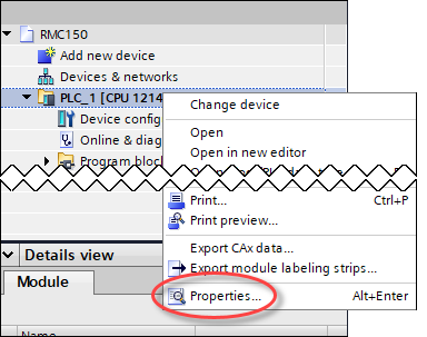
On the General tab, select PROFINET interface.
Choose Set IP address in this project, set the IP address and Subnet mask, then click OK.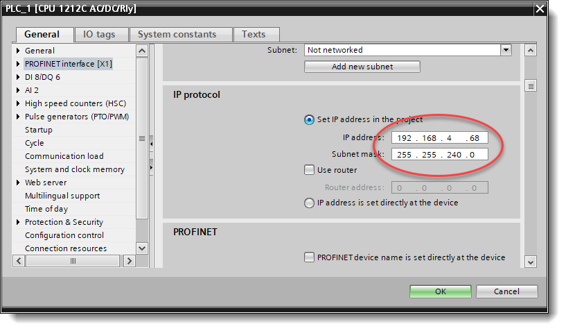
If the RMC GSD files have not yet been added to the hardware catalog, then use the following steps to add them:
On the Options menu, choose Manage general station description files (GSD).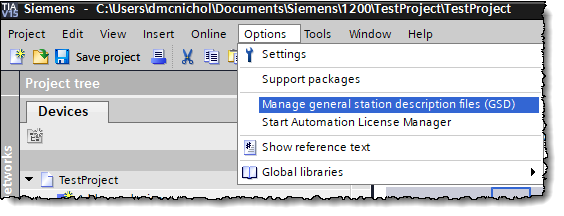
On the Installed GSDs tab, in the Source Path, browse to the PROFINET folder under the RMCTools install folder. This is typically C:\Program Files\RMCTools\PROFINET.
Select the most recent GSD file versions for the RMCs, as shown below. If your software does not accept the most recent version, contact Delta for older versions.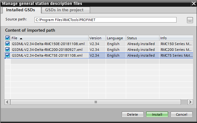
Click Install and follow the instructions to install these GSD files. Click Close when done.
In the project tree, expand Devices & networks and open the Network View.
Use the Hardware Catalog to find the RMC controllers: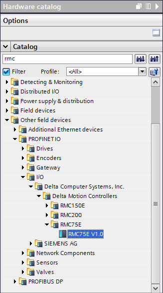
If the RMC device does not show that it is assigned to the PLC, then click the Not assigned link and select the PLC: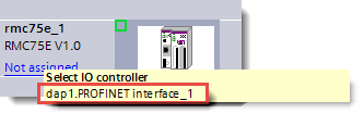
Drag the desired RMC device onto the PROFINET-IO-System network and connect the RMC to the PLC: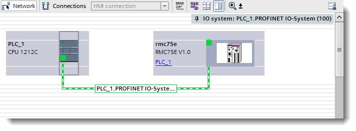
To set the PROFINET device name and IP address settings that the PLC expects for the RMC:
Open the properties for the RMC device and browse to the Ethernet Addresses page as shown below: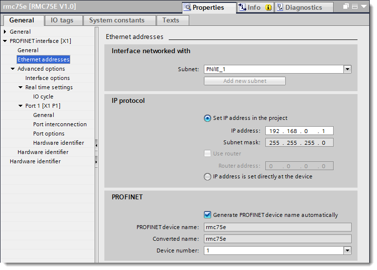
Under PROFINET, make sure that the PROFINET Device Name matches the device name set in the RMC through RMCTools. To change the name, you can either rename the device itself in TIA Portal and leave Generate PROFINET device name automatically checked, or uncheck Generate PROFINET device name automatically and enter the PROFINET device name.
Under IP protocol, if you have set the RMC’s IP address settings through RMCTools and want the S7 to use them as is, then select IP address is set directly at the device. Otherwise, select Set IP address in the project, and the IP address that the S7 will give to the RMC.
To view or change the PROFINET update time for the RMC:
Open the properties for the RMC device and browse to the IO Cycle page as shown below: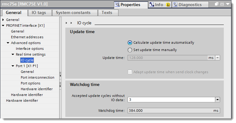
Under Update Time, select a value or accept the automatically-calculated value. The RMC75 and RMC150 support between 2.0 and 512.0 ms. The RMC200 supports between 1.0 and 512.0 ms. A commonly-used update time is 16.0 ms. To set the update time manually, first select Set update time manually.
Under Watchdog Time, the default number of update cycles should typically be used, which is 3 in this case.
Select the Input Data and Output Data lengths as follows. The Input Data corresponds to the Outgoing Cyclic I/O Data in the RMC and the Output Data corresponds to the Incoming Cyclic I/O Data in the RMC.
In the Hardware Catalog under the device you added to the PROFINET network, expand the Inputs folder.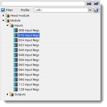
Determine which input module you need based on the number of registers to transfer.
Drag the desired input module onto slot 1 in the RMC’s slot view.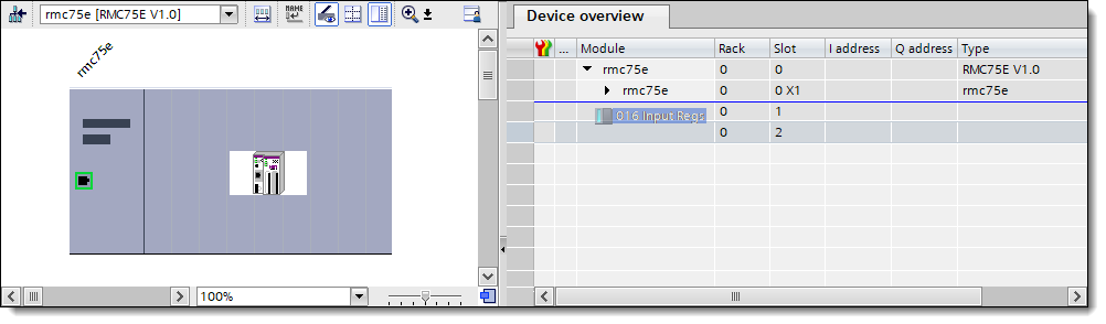
In the Hardware Catalog, expand the Outputs folder.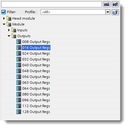
Determine which output module you need based on the number of registers to transfer.
Drag the desired output module onto slot 2 in the RMC’s slot view.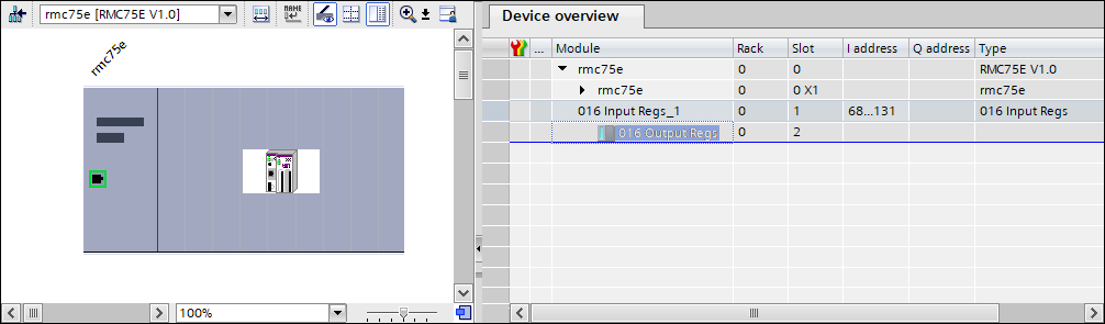
The final module configuration will look similar to the following: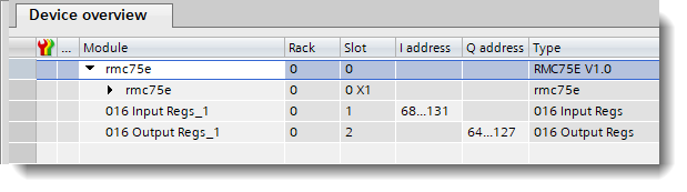
Save and download the configuration to your S7 controller.
Using the Cyclic I/O Data in the S7
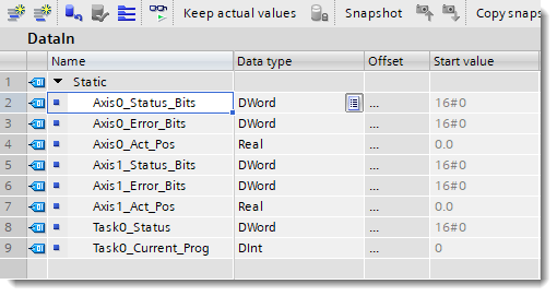
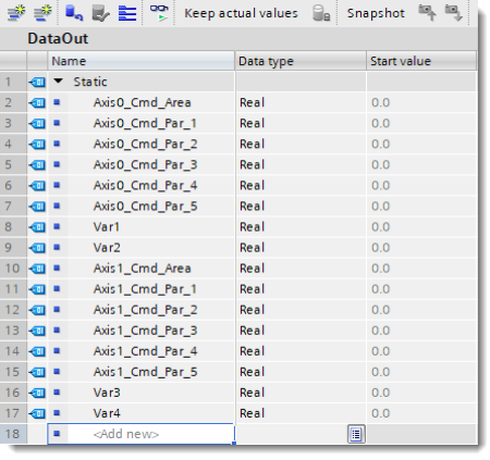
The first step in using cyclic I/O data in the S7 is to define a data block (DB) for each of the Input Data and Output Data. The structure of the Input and Output DBs should match the data defined in the RMC for the Outgoing and Incoming Cyclic I/O Data respectively.
This example matches the data entered in the Indirect Data Map above:
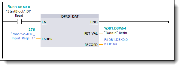
Within TIA Portal, the DPRD_DAT system function (SFC14) is used to get a consistent copy of the Input Data. The following ladder shows SFC14 taking a copy of the input data from the RMC and storing it into DB1.
After the input data has been loaded into DB1 using the DPRD_DAT system function, the S7 program can use this data and should set up the outgoing data in the output DB (DB2 in this example). After the output data has been fully set up, the DPWR_DAT system function (SFC15) is used to send a consistent copy of the data out over PROFINET to the RMC.
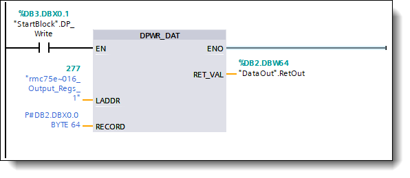
Notice that the RMC’s I and Q data should generally not be accessed directly but should instead go through the DPRD_DAT and DPWR_DAT SFCs in order to ensure that the data is always handled as a consistent block.
Reading and Writing Record Data from the S7
Use the Data Records to read from or write to any location in the RMC. Record Data reads and writes can be performed while the cyclic data exchange is occurring. The maximum Record Data read or write length is 2048 32-bit registers (8192 bytes) for the RMC75 and RMC150, and 4096 32-bit registers (16,384 bytes) for the RMC200.
RMC75 and RMC150:
Fixed Data Records: Data Records 7-255 correspond to the register files 7 -255 in the RMC, as listed in the RMC150 Register Map and RMC75 Register Map. Reads and writes of Data Records 7-255 will begin at element 0 of the file. Fixed Data Records are useful for accessing plot data, the Variable Table, and even the command area.
Custom Data Records: The locations of Data Records 1000-1003 can be specified in the PROFINET Settings Page in RMCTools. This overcomes the Fixed Data Records limitations of starting at element 0. Custom Data Records are useful for accessing any location in the RMC.
RMC200:
Fixed
Data Records
Data Records 0-3 are assigned as listed in the PROFINET
Data Records Address Map. Reads and writes of Data Records always
begins at the first element in the record.
Configurable
Data Records
The user can configure 32 more Data Records in the PROFINET
Data Records Address Map. This is useful for accessing items such
as plot data.
Reading and Writing Record Data
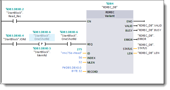
To read and write Record Data, use the RDREC (SFB52) and WRREC (SFB53) system function blocks.
Insert the RDREC (SFB52) or WRREC (SFB53).
At the top of the SFB, type a name of a new Data Block (DB). If it does not exist, after pressing Enter, you will be prompted to create a new one. Choose Yes.
Wire the EN input to turn on as required by your application.
Wire the REQ input so that it will turn on for one scan to trigger the read or write. This can be done with a one-shot.
For the ID, choose the ~Head of the RMC device: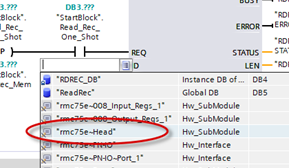
Index is the Data Record number to read from or write to.
Set MLen or Len to four times the number of 32-bit registers to be sent or received. The maximum length is 8192 bytes (2048 32-bit registers) for the RMC75 and RMC150, and 16,384 bytes (4096 32-bit registers) for the RMC200.
Set Record to the Data Block that contains the source or destination data. You must define this Data Block. The contents of the Data Block should match the data area of the RMC.
Wire the Valid, Busy, Error, and Status outputs as required by your application.
RDREC Example
This example reads 8 registers (32 bytes) starting at %MD56.0 for the RMC75E.
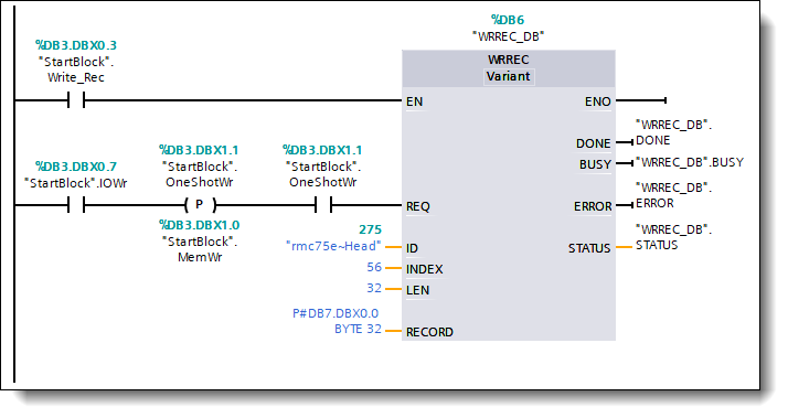
WRREC Example
This example writes 8 registers (32 bytes) starting at %MD56.0 for the RMC75E.
See Also
PROFINET Overview | Using Siemens S7 PLCs via PROFIBUS | Using a PROFINET I/O Connection | Setting up a PROFINET I/O Connection | Using PROFINET Record Data | Handling Broken PROFINET Connections | Troubleshooting PROFINET
Copyright © 2026 Delta Computer Systems, Inc. dba Delta Motion