Several Omron controllers support EtherNet/IP I/O communication. This topic describes how to configure and use the Omron CS1 and CJ2 PLCs to communicate with the RMC via EtherNet/IP I/O. For instructions on using the FINS protocol to communicate with an RMC from an Omron PLC, see the Using Omron Controllers via FINS topic.
Determine Data Size and Number of I/O Connections
The first step is to determine the amount of data to be transferred and the number of I/O connections to set up between the PLC and the RMC:
If you have an RMC75E or RMC150E, you will use one (1) I/O connection that transfers data back and forth between the PLC. See the chart below for the maximum number of registers that can be transferred.
If you have an RMC200, the I/O connection supports 360 registers in each direction. This will typically be enough data for most applications. If you need more data, you will need to use multiple connections (maximum of 3), for as much data as you need, as shown in the chart below. Or, if your PLC is limited to 125/124 registers for the first connection, you may need to use multiple connections. See the chart below for the maximum number of registers that can be transferred with each connection. Keep in mind that the connections are independent of each other, and the data will not be transferred at the same time, even when the RPI may be set to the same value.
I/O Connections and Max Data Size (input is to PLC, output is from PLC)
|
Connection |
RMC75E |
RMC150E |
RMC200 |
|
Connection#1 |
125 input registers 124 output registers |
125 input registers 124 output registers |
360 input registers |
|
Connection#2 |
n/a |
n/a |
125 input registers 124 output registers |
|
Connection#3 |
n/a |
n/a |
125 input registers 124 output registers |
Determine I/O Data Locations in the RMC
EtherNet/IP I/O transfers data back and forth between the RMC and PLC at the Requested Packet Interval (RPI). The user must specify which data items in the RMC should be sent and received. Typically, this is data in the Indirect Data Map.
Set up the Indirect Data map so that one part contains all the data coming from the PLC (Incoming Data), and another part contains all the data going to the PLC (Outgoing Data). Make sure the Incoming and Outgoing Data areas in the Indirect Data Map do not overlap.
The Outgoing Data typically includes RMC status items that the PLC always needs to keep track of, such as actual positions and status bits.
The Incoming Data consists of items that the PLC needs to write to in the RMC. This is typically variables and possibly command registers.
Note:
The Incoming and Outgoing Data locations need not be the Indirect Data
Map. However, the Indirect Data Map is usually the best choice. Other
options are the Variable Table and the command area.
Setting Up the RMC for EtherNet/IP I/O
Do the following in the RMC:
Set the RMC's IP Address
Set up the RMC's IP Address as for any Ethernet connection. See Setting Up the RMC Ethernet for details.
Set Up the Indirect Data Map
In the Project pane, double-click Address Maps, then click Indirect Data Map.
Beginning at item 0 in the Indirect Data Map, choose the items for the Outgoing Cyclic I/O Data.
At some location in the Indirect Data Map after the Outgoing Cyclic I/O Data area, choose the items for the Incoming Cyclic I/O Data, that is, the items that will be sent to the RMC from the PLC. If you are using another location for your Incoming Data, such as the Variable Table or Command Area, you need not set up the Indirect Data Map for the Incoming Data.
If you are using multiple connections to the RMC, repeat this for each connection.
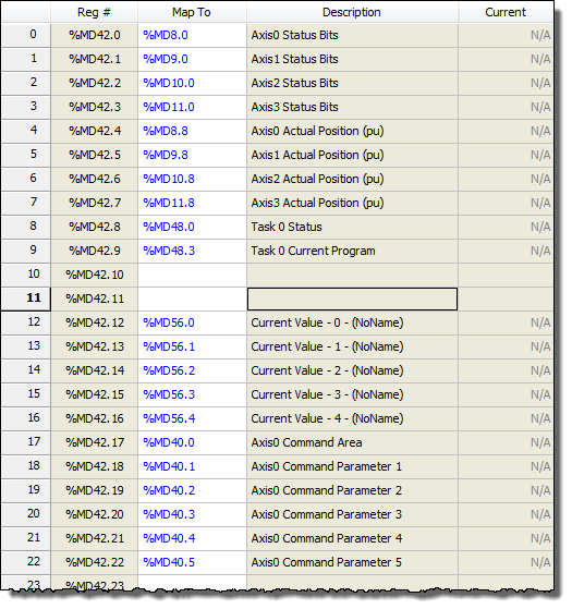
Example
If you have a 4-axis
controller, you may wish to set up the Outgoing Data at the beginning
of the Indirect Data Map to include the Actual Position and the Status
Bits for each axis, in addition to information on Task 0, which perhaps
runs your user programs.
You may also wish to set the Incoming Data, starting at item 12 in the
Indirect Data Map, to go to 5 variables and some of the Axis 0 command
registers. You could then set up the Indirect Data Map like this:
Set the Cyclic I/O Data Locations in the RMC
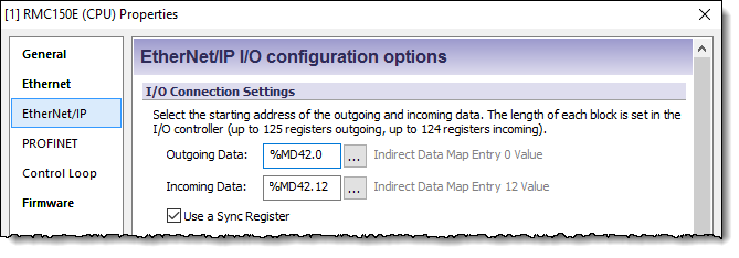
In the Project pane, expand the Modules folder, double-click the CPU module, and choose EtherNet/IP.
Under Outgoing Data, enter the starting location for the outgoing cyclic I/O data. In our example, verify that the location is the Indirect Data Map Entry 0 Value.
Under Incoming Data, enter the starting address for the incoming cyclic I/O data. This should be a location in the Indirect Data Map, the Variable Table, or Command Area as discussed in the Determine I/O Data Locations in the RMC section above.
If you are using multiple connections to the RMC, repeat this for each connection, otherwise, ignore the other connection settings.
For example, the EtherNet/IP Settings Page below shows an RMC150 with the Outgoing Data coming from the Indirect Data map starting at item 0 and the Incoming Data going to the Indirect Data starting at item 12.
Choose Whether to Use a Sync Register
The Sync Register provides a method for the PLC to synchronize the Input Data and Output Data. If you will be writing to the Command Area directly or indirectly via the Indirect Data Map, Delta recommends using the Sync Register.
With a Sync Register, the Incoming Data is not written to the RMC until the Sync Register change. If you prefer to have the Incoming Data be written whenever any value in the Incoming Data changes, choose the option to not use a Sync Register.
For multiple connections, each connection has an individual Sync Register. Keep in mind that the connections are independent of each other, and the data may not be transferred at exactly the same time, even if the Sync Registers are changed simultaneously.
For more details, see Using an EtherNet/IP I/O Connection.
Configuring the Omron Connection
The following procedures describe setting up an EtherNet/IP I/O connection between an Omron communication adapter and an RMC using Omron’s Network Configurator software. These procedures are based off of Network Configurator 3.20. The corresponding Omron documentation for these procedures is in section 6 (Tag Data Link Functions) in the Omron EtherNet/IP Units Operational Manual (W465) manual.
In CX-Programmer, configure the the module with the EtherNet/IP port as follows:
In the project view, double-click IO Table and Unit Setup.
Expand
Main Rack and double-click the
EIP21 module: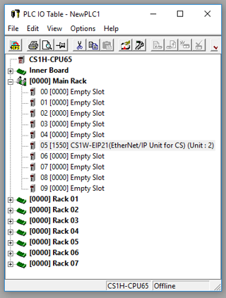
Set
the IP Address, Sub-net
Mask, and Default Gateway,
then click Transfer[PC to Unit]: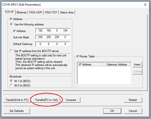
Click
Restart to restart the EIP21 module: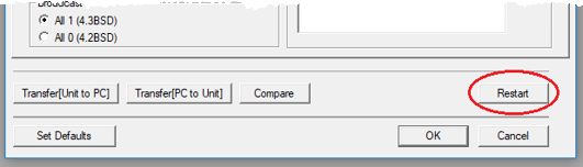
Start the Network Configurator.
If you have an existing EtherNet/IP network that you are adding the RMCs to, then do the following:
Open your existing Network Configurator file.
Skip to step 5.
If this is a new EtherNet/IP network, then do the following:
From the list of EtherNet/IP Hardware on the left side, drag the appropriate communications adapter to the network line on the right side.
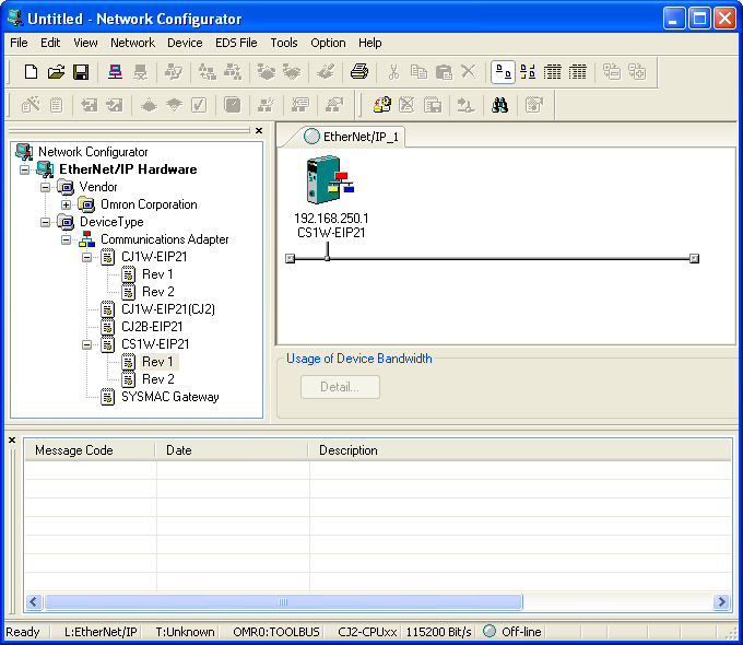
Right-click on the new node in the diagram, and click Change Node Address.
Enter the new Communication Adapter’s IP address to match the address set up in the PLC IO Table and click OK.
Install the RMC EDS files into the Network Configurator.
In Network Configurator, on the EDS File menu, click Install.
Browse to the EDS folder in the RMCTools installation location, which is typically C:\Program Files\RMCTools\EDS\, and click Open to add the EDS file.
Repeat step b to install additional EDS files.
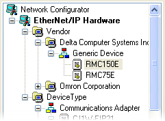
The EtherNet/IP Hardware list should now include the RMC devices you added:
Add the RMC device to your EtherNet/IP network.
From the list of EtherNet/IP Hardware on the left side, drag the appropriate RMC device to the network line on the right side.
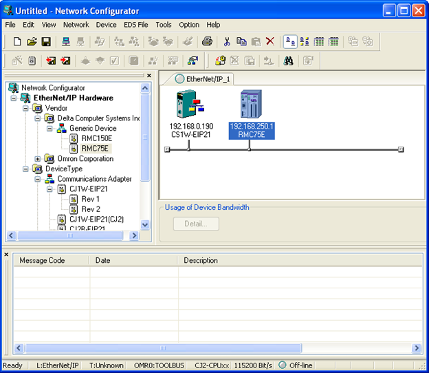
Right-click on the new node in the diagram, and click Change Node Address.
Enter the RMC’s actual IP address, as configured in RMCTools and click OK.
Edit the Device Parameters for the RMC.
Double-click the RMC controller in the network diagram. This will open the Edit Device Parameters window.
|
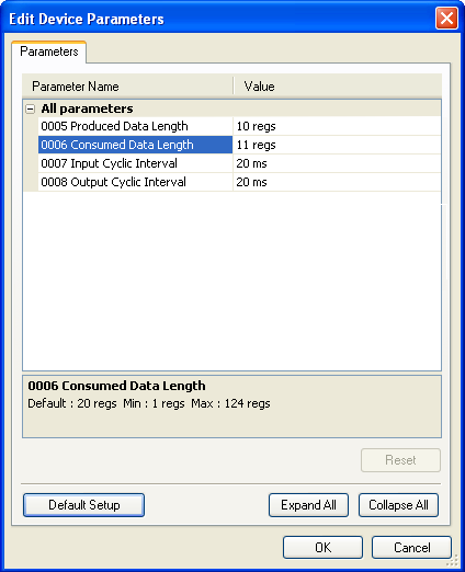
RMC75 and RMC150:
|
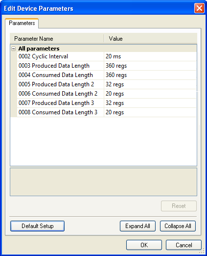
RMC200:
|
RMC75 and RMC150:
For the 0005 Produced Data Length parameter, enter the number of registers that you want the RMC to send cyclically to the PLC. If you chose to use the Sync Register, then this value must include the Sync Register.
For the 0006 Consumed Data Length parameter, enter the number of registers that you want the PLC to send cyclically to the RMC. If you chose to use the Sync Register, then this value must include the Sync Register.
RMC200:
For the 0003 Produced Data Length parameter, enter the number of registers that you want the RMC to send cyclically to the PLC. If you chose to use the Sync Register, then this value must include the Sync Register.
For the 0004 Consumed Data Length parameter, enter the number of registers that you want the PLC to send cyclically to the RMC. If you chose to use the Sync Register, then this value must include the Sync Register.
If you are using multiple connections, set the remaining items for the second and third connections, otherwise other items will be ignored.
Click OK. The cyclic intervals will be set later in the process.
Create Tag Sets for the Input and Output Data
Before establishing an I/O connection, the location for the I/O data in the Omron PLC must be configured. The following procedure describes one way of doing this. However, be aware that the tags must be known about both by CX-Programmer and Network Configurator. Section 6-2-4 Creating Tags and Tag Sets of the Omron EtherNet/IP Units Operational Manual (W465) manual describes other methods of creating tag sets.
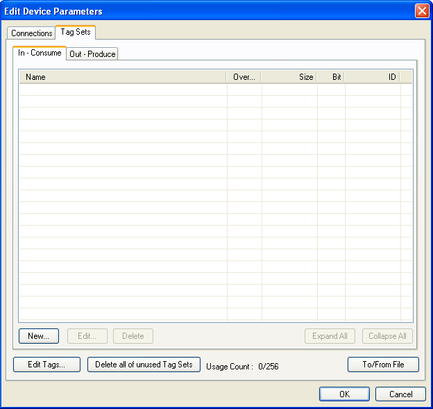
Double-click the Communication Adapter in the network diagram (CS1W-EIP21 in our example), and click the Tag Sets tab. This opens the Edit Device Parameters for the communication adapter to the Tag Sets tab:
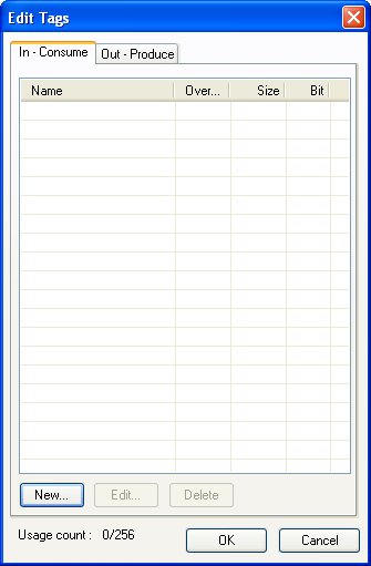
Click Edit Tags. This opens the Edit Tags window:
Add a single tag to the In – Consume tab:
Click the In – Consume tab.
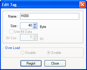
At the bottom of the In – Consume tab, click New.
In the Edit Tag dialog box, enter the Omron destination tag name in the Name box, and enter the length of the RMC’s produced data in bytes in the Size box. This value must be four times the RMC’s 0005 Produced Data Length device parameter above. Notice that for Omron CS1 and CJ1 PLCs, the tag name must an Omron address. An address in the H memory range is recommended to allow direct bit access.
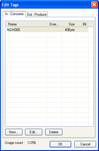
Click OK. If this is the only connection, then click Close if prompted to add another tag. If you have multiple connections, choose to add another tag for each connection, following steps i-iv above.
The In – Consume tab should look like this:
Add a single tag to the Out – Produce tab:
Click the Out – Produce tab.
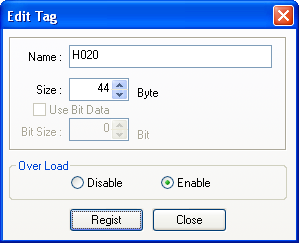
At the bottom of the Out – Produce tab, click New.
In the Edit Tag dialog box, enter the Omron source tag name in the Name box, and enter the length of the RMC’s consumed data in bytes in the Size box. This value must be four times the RMC’s 0006 Consumed Data Length device parameter above. Notice that for Omron CS1 and CJ1 PLCs, the tag name must be an Omron address. An address in the H memory range is recommended to allow direct bit access.
Click OK.
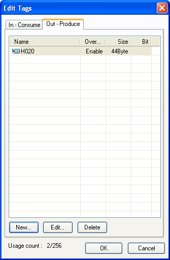
If this is the only connection, then click Close if prompted to add another tag. If you have multiple connections, choose to add another tag for each connection, following steps i-iv above.
The Out – Produce tab should now look like this:
In the Edit Tags, window, click OK.
When prompted to register the new Tags as Tag sets, click Yes.This will add the new tags as tag sets:
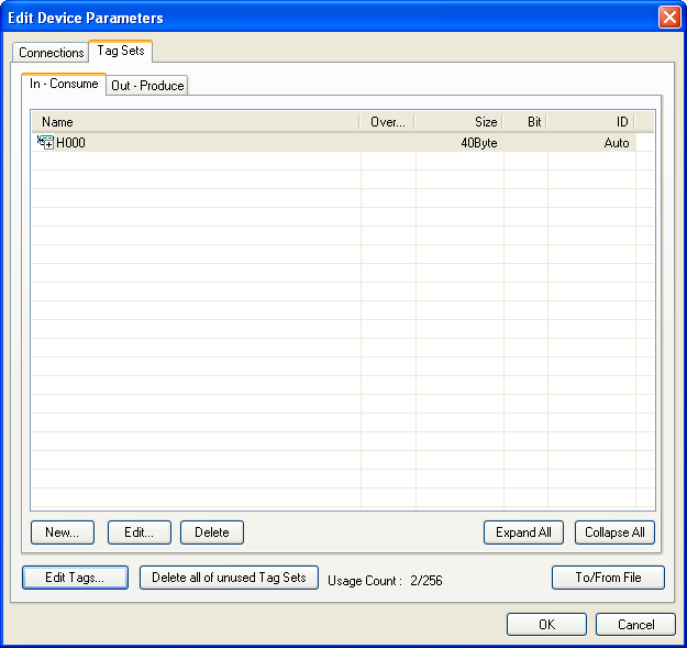
There are now two tag sets that have been registered. These tag sets will be used when creating the connection in the next step.
Create a connection to the RMC
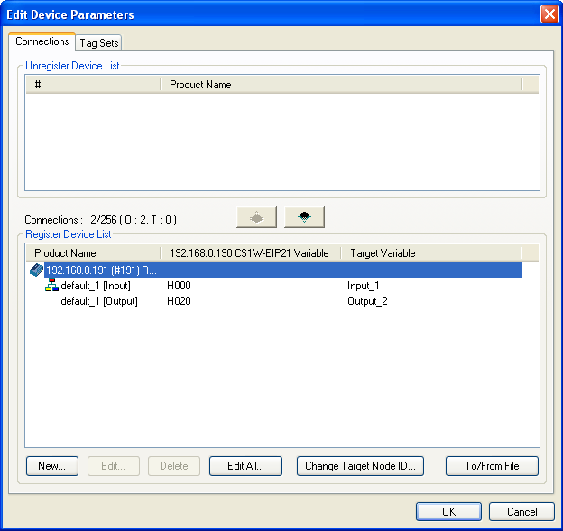
In the Edit Device Parameters window for the Communication Adapter (CS1W-EIP21 in this example), click the Connections tab.
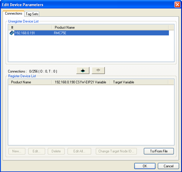
The RMC is listed in the Unregister Device List. In order to establish an I/O connection with this device, we must register the device, and then add a new connection.
Select
the RMC in the Unregister Device List,
and click the down arrow button  to register it. The RMC will now appear in the Register
Device List:
to register it. The RMC will now appear in the Register
Device List:
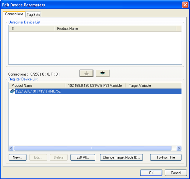
Select the RMC in the Register Device List, and click New. This opens the Edit Connection window:
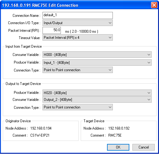
Fill in
the fields in this dialog box as follows:
|
Field |
Value |
|
Connection Name |
Optionally assign a user-readable name for this connection. |
|
Connection I/O Type |
Select Input/Output. The other options are only for use by advanced users. |
|
Packet Interval (RPI) |
Select the desired update rate. A commonly used RPI is 20.0 ms. Very low RPIs may flood the network, and reduce network reliability. |
|
Timeout Value |
Select Packet Interval (RPI) x 4, although for the minimum RPI of 2.0 ms, the Omron only supports Packet Interval (RPI) x 8 or higher. |
|
Input from Target Device Consume Variable |
Select the input tag set created in the previous steps, H000 – [40Byte] in this example. |
|
Produce Variable |
Leave this set to the default, Input_1 – [40Byte] in this example. |
|
Connection Type |
In most applications this should be set to Point to Point connection. In advanced applications that will share the data in multiple controllers, Multi-cast connection must be used. |
|
Output to Target Device Produce Variable |
Select the output tag set created in the previous steps, H020 – [44Byte] in this example. |
|
Consume Variable |
Leave this set to the default, Output_2 – [44Byte] in this example. |
|
Connection Type |
Select Point to Point connection. |
Click OK.
If you
have multiple connections, choose to add another tag for each connection,
following steps c - e above.
The Connections tab may now look something like this:
Add additional RMC devices to your EtherNet/IP network.
Repeat steps 6-9 above for each additional RMC device.
Download the Network Configuration
On the Option menu, point to Select Interface, and then click Ethernet I/P.
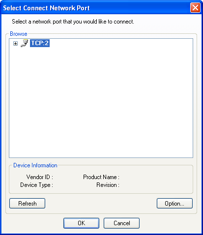
On the Network menu, click Connect.
In the Select Connect Network Port window, select the Ethernet interface to use (which will most often be just one), and click OK.
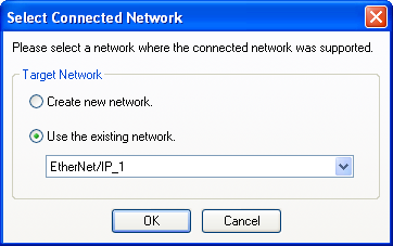
In the Select Connected Network, select to use the existing network you just created and click OK.
On the Network menu, click Download. Answer Yes to any prompts.
Save the Network Configuration
On the File menu, click Save. Follow the instructions to save the network configuration.
Performing Communications
Once the EtherNet/IP connection is configured and applied to the PLC, the communications will automatically start, assuming the PLC and RMC are both on a properly set up Ethernet network. Notice that the Omron will communicate even when it is in Program mode.
Reading Data from the RMC
This data will automatically update each Requested packet interval, and you can use the data as you wish. You cannot write to the Input Data. The Input Data will contain the Indirect Data from the RMC. However, if you selected to use the Sync Register, the first item in the Input Data array will be the SyncIn value, followed by the Indirect Data from the RMC.
The SyncIn is used only for synchronizing commands with the logic, as explained below. The SyncIn and SyncOut registers are only visible in the PLC. They are not visible in RMCTools. If you are using multiple connections, keep in mind that the connections are independent of each other, and the data may not be transferred at exactly the same time, even if the Sync Registers are used and are changed simultaneously.
Writing to the RMC - General
For each connection without a Sync Register, the Output Data is written to the RMC when any value in the Output Data changes.
For each connection with a Sync Register, the Output Data is sent to the RMC at each Requested Packet Interval, but the RMC ignores it until the SyncOut register changes. The first item in the Output Data array is the SyncOut register, followed by the registers that will be sent to the Incoming Data location in the RMC. Use the following procedure to write to the RMC with a Sync Register:
Wait Until the Sync In and Sync Out Registers Match
If they do not match, then this means that another write is in progress.
Write to the Output Data
Write the desired to the Output Data array.
Change the Sync Out Register
The easiest way to do this is to add one to it. However, you must take care to handle overflowing this register (the Sync register is a REAL). One method is to add one and then MOD it with some large number, such as 10000. This will make the register count from 0 to 9,999, and then wrap back down to 0 without an error.
Wait Until the Sync In and Sync Out Registers Match
This indicates that the RMC has received the data and processed it.
If you are using multiple connections with sync registers, you must change the Sync Register independently for each connection. The connections are independent of each other, and the data may not be transferred at exactly the same time, even if the Sync Registers are changed simultaneously.
See Using an EtherNet/IP I/O Connection for further details.
Sending Commands to the RMC
If you are writing to the Command Area, either directly or via the Indirect Data Map, Delta recommends using a Sync Register and following the procedure below to send commands to the RMC. The Output Data is sent to the RMC each RPI, but the RMC ignores it until the SyncOut register changes. The first item in the Output Data array is the SyncOut register, followed by the registers that will be sent to the Incoming Cyclic I/O Data location in the RMC.
Wait Until the Sync In and Sync Out Registers Match
If they do not match, then this means that another write is in progress.
Clear Old Commands from the Command Registers
Clear old commands from the command registers in the Output Data. Otherwise, when the Sync Out register is changed, the commands would be re-issued. One method of clearing the old commands is to fill the Output Data array with zeroes (except the SyncOut value).
Write to the Command Registers
Write the Command registers and all required command parameters to the Output Data for all commands you want to issue. You can issue up to one command per axis. Leave the Command register set to 0 for each axis that will not receive a command.
For example, if a portion of the Output Data is going to the Command Area for Axis 0, and you wish to issue a Move Absolute Command (20) to Axis 0 with a position of 6.7, a Speed of 3, and Accel and Decel of 50, you would write the following:
|
Value |
|
20 (for a move Absolute Command) |
|
6.7 (Position) |
|
3 (Speed) |
|
50 (Accel) |
|
50 (Decel) |
|
0 (Direction) |
Use the online help for each command to find out how many parameters a command has and what they mean. Make sure to write to all the parameters that the command uses. You do not need to write to command parameters that are not used by the command.
Change the Sync Out Register
The easiest way to do this is to add one to it. However, you must take care to handle overflowing this register (the Sync register is a REAL). One method is to add one and then MOD it with some large number, such as 10000. This will make the register count from 0 to 9,999, and then wrap back down to 0 without an error. Take care to ensure that you only update the Sync Out Register once so that the commands do not get re-issued.
Wait Until the Sync In and Sync Out Registers Match
This indicates that the RMC has received the command and issued it. It is important to wait until the SyncIn and SyncOut match before using the status bits in the Input Data (if the Input Data includes any status bits). See the Using an EtherNet/IP I/O Connection topic for how problems can occur if this step is ignored.
For multiple connections to one RMC, each connection has an individual Sync Register. The connections are independent of each other, and the data may not be transferred at exactly the same time, even if the Sync Registers are changed simultaneously. Therefore, it is best practice that if commands need to be sent simultaneously, that they are sent in the same Output Data block.
See Using an EtherNet/IP I/O Connection for further details.
Reading and Writing other registers
To read and write other registers in the RMC that are not included in the Incoming or Outgoing Cyclic I/O Data, you can use the SEND and RECV instructions as described in Using Omron Controllers via FINS. EtherNet/IP I/O and the SEND and RECV instructions can be used simultaneously.
Another option for writing to other RMC registers is to create user programs that move data from the variable table to other RMC registers.
See Also
EtherNet/IP Overview | Using Omron Controllers via FINS
Copyright © 2025 Delta Computer Systems, Inc. dba Delta Motion