The Mitsubishi Procedure Exist Ethernet protocol is for Mitsubishi's Q-series QJ71E71-100 Ethernet module and the FX3U PLC. For communication with other Mitsubishi PLC modules, such as CPUs with built-in Ethernet, see Using the Mitsubishi Q-Series PLC with the RMC.
The QJ71E71-100 and FX3U support several communication protocols. The RMC75E, RMC150E and RMC200 support the Fixed Buffer communication with the Procedure Exist control method. It allows the Mitsubishi PLC to read and write binary data from an RMC over Ethernet. The RMC requires that the data sent via the Procedure Exist method is formatted as described in this topic. The Procedure Exist protocol is described in chapter 7 of the Q Corresponding Ethernet Interface Module User's Manual (Basic). The manual part number is SH (NA)-080009-I. It is also described in the FX3U manual User explanations for FX3U-ENET Ethernet Block, manual no. JY997D18101.
The RMC uses port number 7171 hex (29,041 in decimal) for the Procedure Exist protocol.
A sample program for the Q-Series Procedure Exist method is available on the downloads page of Delta's website at https://deltamotion.com/dloads. This should be used as a starting point for any Mitsubishi Q-series program using the QJ71E71-100 Ethernet module and an RMC.
Note:
The RMC can also communicate with the Mitsubishi Q-series PLC via the QJ71MT91
Ethernet Modbus/TCP module. Modbus/TCP is a complete protocol and therefore
using the QJ71MT91 requires less programming than using the QJ71E71-100.
Consequently, the QJ71MT91 may be slightly easier to use with the RMC.
The disadvantage is that the QJ71MT91 it is not as widely used as the
QJ71E71-100. A sample program for using the QJ71MT91 is available on the
downloads page of Delta's website.
Configuring the Q-Series
Mitsubishi’s ”Q Corresponding Ethernet Interface Module User's Manual (Basic)” (manual part number SH (NA)-080009-I) describes how to set up QJ71E71-100. It is very detailed, but is very large and may seem difficult. The sections below describe the settings necessary to use the QJ71E71-100 to communicate with the RMC.
The instructions below are from GX Developer version 8.25B.
1. I/O Assignment Settings
First, set the I/O settings. This is described in section 4.5.1 of the Q Corresponding Ethernet Interface Module User's Manual (Basic). Notice that there are no Switch settings to set for this module.
2. Network Parameter Settings
This is described in section 4.6 of the Q Corresponding Ethernet Interface Module User's Manual (Basic).
In the Project Data List, double-click Network Param, then click MELSEC/Ethernet. For each QJ71E71-100 module, set the following parameters:
|
Network Type |
Set to Ethernet |
|
Starting I/O Number |
Set this to the head address of the Ethernet module |
|
Network No. |
See section 4.6 of the manual (Set to 1) |
|
Total Stations |
— |
|
Group No. |
Set to 1 |
|
Station No. |
Set to 1 |
|
Mode |
Set to On line |
|
Operational Settings |
Communication data Code: Binary Code Initial Timing: Do not Wait for Open IP Address: enter the IP Address of the QJ71E71-100. Send frame setting: Ethernet(V2.0) Enable Write at RUN time: cleared TCP Existence confirmation setting: Use the KeepAlive |
|
Initial Settings |
No settings required here. |
|
Open Settings
|
For each RMC you wish to communicate with, you must set up a paired connection. To do so, on one row, set the following: Protocol: TCP Open System: Active Fixed Buffer: Receive Fixed Buffer communication procedure: Procedure Exist Paring open: Enable Existence confirmation: Confirm Host Station Port No.: 7171 hex (29,041 in decimal) Transmission device IP address: Set this to the IP Address of the RMC Transmission target device Port No.: 7171 hex (29,041 in decimal) Because Pairing open is set to Enable, the next row will automatically be set identically, except the Fixed Buffer will be set to Send. Notice that each QJ71E71-100 can communicate with up to 8 RMCs. |
Opening a Connection on the Q-Series
Before the PLC can communicate with the RMC, the IP connection must be opened using the ZP.OPEN instruction, described in section 10.8 of the Q Corresponding Ethernet Interface Module User's Manual (Basic). Both connections of the pair (Send and Receive) must be opened individually.
The port number must be 7171 hex (29,041 in decimal).
Closing a Connection on the Q-Series
To close the IP connection to the RMC, use the ZP.CLOSE instruction, described in section 10.5 of the Q Corresponding Ethernet Interface Module User's Manual (Basic). Both connections of the pair (Send and Receive) must be closed individually.
Writing to the RMC with the Q-Series
Use the ZP.BUFSND Instruction to write to registers in the RMC. It is described in section 10.4 of the Q Corresponding Ethernet Interface Module User's Manual (Basic). The RMC requires that the Send Data of the BUFSND instruction is in the format shown below.
|
TxCount
(16 bits) |
0
(16 bits) |
Register File (16 bits) |
Register Element (16 bits) |
Data Item 1
(32 bits) |
Data Item 2
(32 bits) |
… |
Data Item n
(32 bits) |
Description:
|
TxCount |
The number of 16-bit words written, not including this word.
|
|
0 |
This word must be 0. |
|
Register File |
This is the file number of the register’s address in IEC format. For example, for %MD8.12, the file number is 8. |
|
Register Element |
This is the element number of the register’s address in IEC format. For example, for %MD8.12, the element number is 12. |
|
Data Time 1 |
The RMC has 32-bit registers. Therefore, you can only write 32-bit words. Most RMC registers are floating-point; a few are integers. |
|
Data Item n |
To write n 32-bit registers to the RMC, make sure the TxCount is correct. It should be (2 x n) + 3. |
Example
A programmer wishes to write 5 values to the variable table in the RMC75 (address %MD56.0). These values are: 32.876, 1.0, 12.0, 5.432, 862.0.
The send data for the ZP.BUFSND instruction would be as follows:
|
13 (16 bits) |
0 (16 bits) |
56 (16 bits) |
0 (16 bits) |
32.876 (32 bits) |
1.0 (32 bits) |
12.0 (32 bits) |
5.432 (32 bits) |
862.0 (32 bits) |
Reading from the RMC with the Q-Series
To read registers from the RMC, use the ZP.BUFSND instruction to send a read request and then use the ZP.BUFRCV instruction to read the received data. The ZP.BUFRCV instruction is described in section 10.2 of the Q Corresponding Ethernet Interface Module User's Manual (Basic).
Writing the Read Request
To send a request a read from the RMC, the send data of the ZP.BUFSND instruction must be formatted as shown below. Each box is a 16-bit word.
|
3 (16 bits) |
Read Count (16 bits) |
Register File (16 bits) |
Register Element (16 bits) |
Description:
|
3 |
This is actually TxCount, the number of 16-bit words written, not including this word. This value must be 3 when requesting a read. |
|
Read Count |
This is the number of 32-bit registers to be read from the RMC, starting at the address given by the file and element. The Read Count may be between 1 and 382. |
|
Register File |
This is the file number of the address of the first register to be read. For example, for %MD8.12, the file number is 8. |
|
Register Element |
This is the element number of the address of the first register to be read. For example, for %MD8.12, the element number is 12. |
Receiving the Returned Data
After the write request is sent, the RMC will return the requested data. The QJ71E71 buffer memory location 20485 indicates whether data is being received. The bit in memory location 20485 corresponding to the current connection can be used to indicate when to read the receive buffer.
To read the receive buffer, use the ZP.BUFRCV instruction. The returned data is in the format shown below:
|
16-bit Count
(16 bits) |
32-bit Read Count (16 bits) |
Data Item 1
(32 bits) |
Data Item 2
(32 bits) |
… |
Data Item n
(32 bits) |
Description:
|
16-bit Count |
This is the number of 16-bit words read from the buffer. |
|
32-bit Read Count |
This is the number of 32-bit registers that the RMC returned. |
|
Data Item 1-n |
This is the returned data. |
Communicating Directly over TCP
For RMC 75E/150E firmware versions prior to 3.31.0, in applications where none of the RMC’s protocols are supported by the master controller, but direct communication over TCP is allowed, Delta recommended that the Mitsubishi Procedure Exist protocol be implemented by the user manually. The remainder of this topic describes how to manually implement the Mitsubishi Procedure Exist protocol for communication with RMCs. The RMC75E/150E firmware versions 3.31.0 and newer and the RMC200 support the Delta Motion Control Protocol (DMCP), which is the preferred method of manual direct communication over TCP.
The RMC listens for Procedure Exist connections on TCP port hexadecimal 7171 (decimal 29041). The client TCP port number can be any valid port number. This protocol is a request/response protocol, meaning that the RMC will not send any data unless it receives a packet requesting that it do so.
All multiple-byte fields are encoded with the least-significant byte first. For example, a Packet Length value of 3 would be encoded as 03 00, and a 32-bit data value of 0x11223344 would be encoded as 44 33 22 11.
Writing Data to the RMC:
Writing to one or more registers in the RMC requires the following 2-packet sequence:
First, the client sends the following packet to the RMC:
|
Offset |
Data (hex) |
Description |
|
0-1 |
60 00 |
Sub-Header. These 2 bytes should always have these values in a write request. |
|
2-3 |
mm nn |
Packet Length. This value holds the number of 16-bit words in this packet, not including this field and the sub-header. For writing N registers to the RMC, this register will hold 3+2xN, since each RMC register uses 32 bits, or two 16-bit words. |
|
4-5 |
00 00 |
Must be Zero. These two bytes must be zero (0) to indicate a write. |
|
6-7 |
ff ff |
Register File. This value holds the file portion of the address of the first register to write to. For example, for the IED address %MD12.2, this field would be 0C 00. |
|
8-9 |
ee ee |
Register Element. This value holds the element portion of the address of the first register to write to. For example, for the IEC address %MD12.2, this field would be 02 00. |
|
10-... |
... |
Data. The values of each 32-bit register to write should follow the above header, with each register encoded in 4 bytes ordered from the least- to most-significant byte. |
The RMC will respond to this request with the following packet:
|
Offset |
Data (hex) |
Description |
|
0 |
E0 |
Acknowledge. Indicates that the packet is an acknowledgement. |
|
1 |
rr |
Response Code. Indicates whether the write was successful or not. See the Response Codes section below. |
Reading Data from the RMC:
Reading from one or more registers in the RMC requires the following 4-packet sequence:
The client sends the RMC a read request:
|
Offset |
Data (hex) |
Description |
|
0-1 |
60 00 |
Sub-Header. These 2 bytes should always have these values in a read request. |
|
2-3 |
03 00 |
Packet Length. This value holds the number of 16-bit words in this packet, not including this field and the sub-header. For read requests, this field will always be 03 00. |
|
4-5 |
mm nn |
Read Count. This value holds the number of 32-bit RMC registers to read. This value cannot be greater than 382. |
|
6-7 |
ff ff |
Register File. This value holds the file portion of the address of the first register to read from. For example, for the IEC address %MD12.2, this field would be 0C 00. |
|
8-9 |
ee ee |
Register Element. This value holds the element portion of the address of the first register to read from. For example, for the IEC address %MD12.2, this field would be 02 00. |
The RMC acknowledges the request with the following short packet:
|
Offset |
Data (hex) |
Description |
|
0 |
E0 |
Acknowledge. Indicates that the packet is an acknowledgement. |
|
1 |
rr |
Response Code. Indicates whether the read was successful or not. See the Response Codes section below. |
If the response above is success (00), then the RMC will then send a second packet, holding the data requested:
|
Offset |
Data (hex) |
Description |
|
0-1 |
60 00 |
Sub-Header. These 2 bytes will always have these values in a read response. |
|
2-3 |
mm mm |
Packet Length. This value holds the number of 16-bit words in this packet, not including this field and the sub-header. For reading N registers from the RMC, this register will hold 1+2xN, since each RMC register uses 32 bits, or two 16-bit words. |
|
4-5 |
nn nn |
Read Count. This value holds the number of 32-bit RMC registers that were read. This will match the Read Count field in the read request. |
|
6... |
... |
Data. The values of each register that was read will follow the above header, with each register encoded in 4 bytes ordered from the least- to most-significant byte. |
Finally, the client must acknowledge the RMC’s read response with the following simple packet:
|
Offset |
Data (hex) |
Description |
|
0 |
E0 |
Acknowledge. Indicates that the packet is an acknowledgement. |
|
1 |
00 |
Response Code. Indicates success (00). |
Register Addresses
This protocol uses the RMC’s two-level file/element addressing format. See the IEC Addressing topic describes how this addressing format works.
Response Codes
Each acknowledge packet holds a response code, indicating whether the requested transaction was completed successfully or not. The RMC uses the following response codes:
|
Response Code (hex) |
Description |
|
00 |
Success. |
|
40 |
Protocol Error. Indicates that the request violated the protocol described above in one of the following ways:
|
|
50 |
Bad Sub-header. A request packet did not start with 60 00. |
Example 1: Writing a Single Register
In this example, the client will write the value 0x11223344 to variable 0 (%MD56.0) on and RMC75E. Therefore, the Register File is 56, the Register Element is 0, and the Packet Length is 3+2xN or 5. Entering these values into the write request packet structure with the least-significant bytes first, gives us the following packet:
60 00 05 00 00 00 38 00
00 00 44 33 22 11
After the RMC has successfully received and processed this write request, it will respond with the following packet:
E0 00
Notice that the last byte is the response code, with 00 meaning success.
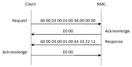
Example 2: Reading a Single Register
In this example, the client will read a value from variable 0 (%MD56.0) on an RMC75E. Therefore, the Register File is 56, and the Register Element is 0. Supposing that variable 0 held the value 0x11223344, then the following packets would be sent between the controllers:
See Also
RMC Ethernet Protocols | Ethernet Overview | Using the Mitsubishi Q-Series PLC with the RMC
Copyright © 2026 Delta Computer Systems, Inc. dba Delta Motion