Character: ?
Decimal: 63
Hexadecimal: 0x3F
Command Value: Extended Link Value
Note: This command is supported in RMC100 CPU firmware dated 20010420 or newer.
Note: This command should only be used in the Event Step table. This command does nothing when issued directly from the PLC.
The Poll (?) command modifies the operation of most link types (exceptions are listed below). This command can only be issued in the Event Step table and affects the link type on the same step as the Poll command.
The Poll command is useful in applications where it is necessary to check for two or more conditions at the same time. For instance it may be required to start a move and then wait until the axis is in position or an error bit is set.
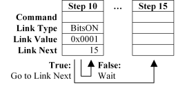
When a link type is encountered without this command, the sequence will wait until the condition is true before proceeding. No other steps are run on that axis’s step sequence until the condition is met, as shown below:

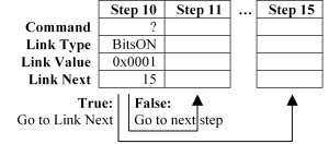
When a link type is encountered with this command, then one of two steps will be run next. If the condition is true, then the step number indicated in the Link Next field will be run. If the condition is false, then the next step (current step plus one) will be run. This is shown below:

When the Poll command is executed, the Command Value is stored in the Extended Link Value, in the same way as in the Set Extended Link Value (l) command. This allows polling of link types that require the Extended Link Value to be set. Because most link types do not use the Extended Link Value, the Command Value can usually be left at zero (0).
Note: Only one polled link type is evaluated per control loop (1 or 2 ms).
The following link types should not be used with the Poll command:
These link types do not work with the Poll command because the timer or counter is restarted each time the link type is encountered in the sequence. An alternative for controlling time in a polled loop is to use the Timer (T and t) link types.
These link types detect rising or falling edges in the current control loop. However, because a polled loop will take more than one control loop, rising or falling edges will likely be missed. Use the level-sensitive InputHigh (O) and InputLow (o) link types instead.
These links types already define both true and false actions, and therefore should not be used with the Poll command.
These links types already define both true and false actions, and therefore should not be used with the Poll command.
This link type will already take a link immediately in all cases and therefore should not be used with the Poll command.
Example 1:
The user wants to make a move to position 4000, and wants to know when either the axis is in position or an overdrive error occurs. The following Event Step sequence accomplishes this using the Poll (?) command:
|
|
Step 10 |
Step 11 |
Step 12 |
Step 13 |
… |
Step 15 |
|
Mode |
0x0081 |
0x0081 |
0x0081 |
0x0081 |
|
0x0000 |
|
Accel |
100 |
100 |
100 |
100 |
|
0 |
|
Decel |
100 |
100 |
100 |
100 |
|
0 |
|
Speed |
10000 |
10000 |
10000 |
10000 |
|
0 |
|
Command Value |
4000 |
0 |
0 |
0 |
|
0x0001 |
|
Command |
G |
? |
? |
|
|
[ |
|
Commanded Axes |
Default |
Default |
Default |
Default |
|
Default |
|
Link Type |
DelayMS |
BitsON |
BitsON |
DelayMS |
|
DelayMS |
|
Link Value |
0 |
0x1000 |
0x0001 |
0 |
|
0 |
|
Link Next |
11 |
15 |
14 |
11 |
|
0 |
Step 10 starts the move to 4000, and links immediately using the DelayMS (D) link type to step 11.
Step 11 checks for an overdrive error. It does this by doing a polled BitsON (B) link type for the Overdrive Error bit (0x1000) of the Status word on the current axis. If this error bit is set, then control goes to the step indicated by the Link Next: step 15. Otherwise, control proceeds to the next step: step 12. Notice that without the Poll (?) command, this link type would wait indefinitely until an overdrive error occurs and would otherwise never proceed to step 12.
Step 12 checks the In Position bit (0x0001) of the Status word, also using the BitsON (B) link type. So, if the axis is in position, control passes to step 14, otherwise control passes to the next step: step 13.
Step 13 links immediately back to step 11 to repeat the polling loop. Notice that this extra step does take one control loop to process and therefore increases the time taken to process the entire polling loop by one control loop (1 or 2 ms).
Step 15 will be jumped to when an Overdrive Error occurs. It simply turns on discrete output 0, perhaps to indicate the overflow to the operator in the form of a red light.
To summarize, the above sequence starts a move to position 4000, jumps to step 15 if an overdrive error occurs, jumps to step 14 if the axis gets in position, and loops through steps 11-13.
Now, compare this method of implementing a polling loop with the one used in the next example, which is a little more difficult to follow but removes the need for the extra do-nothing step in the polling loop (step 13 above).
Example 2:
This example offers an alternative approach to the same problem as in the previous example: move to position 4000, detect either when the axis is in position or when an overdrive error occurs. It is a little more difficult to follow, but removes one step from the polling loop, therefore reducing the amount of time taken to catch any condition. Keep in mind that for many applications, this slight gain in performance will not justify the reduction in clarity:
|
|
Step 10 |
Step 11 |
Step 12 |
… |
Step 15 |
|
Mode |
0x0081 |
0x0081 |
0x0081 |
|
0x0000 |
|
Accel |
100 |
100 |
100 |
|
0 |
|
Decel |
100 |
100 |
100 |
|
0 |
|
Speed |
10000 |
10000 |
10000 |
|
0 |
|
Command Value |
4000 |
0 |
0 |
|
0x0001 |
|
Command |
G |
? |
? |
|
[ |
|
Commanded Axes |
Default |
Default |
Default |
|
Default |
|
Link Type |
DelayMS |
BitsON |
BitsOFF |
|
DelayMS |
|
Link Value |
0 |
0x1000 |
0x0001 |
|
0 |
|
Link Next |
11 |
15 |
11 |
|
0 |
Step 10 starts the move to 4000, and links immediately to step 11.
Step 11 checks for the Overdrive Error bit (0x1000) of the Status word on the current axis. If this error bit is set, control goes to step 15, otherwise control goes to step 12.
Step 12 checks the In Position bit (0x0001) of the Status word. Notice that, unlike the previous example, the BitsOFF (b) link type is used instead of the BitsON (B) link type. Therefore, if the In Position bit is off—that is, the axis is not yet in position—then the Link Next is taken back to step 11 and the polling continues. Otherwise, if the In Position bit is not off—that is, it is on and the axis is in position—then control proceeds to the next step: step 13.
Step 15 will be jumped to when an Overdrive Error occurs. It simply turns on discrete output 0, perhaps to indicate the overflow to the operator in the form of a red light.
To summarize, the above sequence starts a move to position 4000, jumps to step 15 if an overdrive error occurs, and otherwise jumps to step 13 when the axis gets in position.
Here is a summary of the advantages and disadvantages of doing a polled loop using this method versus the method shown in Example 1:
The advantage of this method is that both conditions will be checked every two control loops since there are only two steps in the polling loop (steps 11 and 12).
The disadvantage of this method is that many users will find it confusing to have to reverse the sense of the last condition in the polling loop. That is, the user has to use the BitsOFF (b) link type instead of the more intuitive BitsON (B) link type.
Copyright (c) 1997-2015 by Delta Computer Systems, Inc.