Overview
The analog modules for the RMC can read across voltage or current ranges. To switch between the four voltage ranges, only the Configuration word of the axis needs to be changed and saved to the Flash. To switch to the one current range, the same parameter needs to be changed and one external jumper needs to be attached. Read the appropriate section below for details on your particular transducer type.
Using Voltage Feedback Transducers
Voltage feedback transducers can be connected directly to the +In and -In connections for the desired channel. The Res connection is unused for voltage transducers. The following configuration is recommended:

TIP: If you are using a 10V transducer output, but are only using values in the low 5V, it is recommended that you select a 5V setting to increase the resolution of the analog to digital conversion.
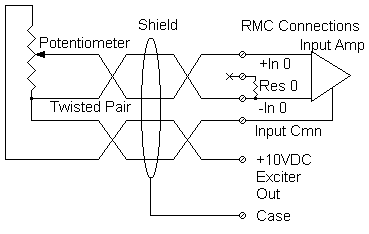
Using the Exciter Output Pin with Potentiometer Feedback
An exciter output pin is provided on the RMC analog modules as a convenience and also to increase the accuracy of the analog to digital conversion. This pin generates +10V with respect to the CMN pin. If a potentiometer type transducer is used, the following configuration is recommended:

Because the exciter voltage is the same voltage used as a comparison for the analog to digital conversion, the transducer is protected from being affected by increases in this positive voltage supply.
Using Current Feedback Transducers
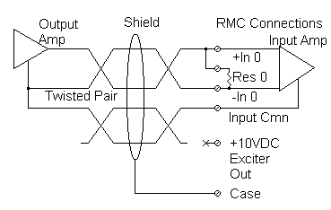
Current feedback transducers are connected in the same way as voltage transducers except that a jumper must be inserted between the +In and Res connections. This places a resistor internal to the RMC across the two inputs, thus converting the current to a voltage input. The following wiring diagram shows a suggested configuration:

Analog Input Ranges
See the COUNTS topic for detailed information on the maximum and minimum limits of the various analog input ranges.
See also:
Analog Transducer Configuration
Using Analog Channels as Position Inputs
Using Analog Channels as Velocity Inputs
Using Analog Channels as Pressure Inputs
Using Analog Channels as Differential Force Inputs
Copyright (c) 1997-2015 by Delta Computer Systems, Inc.