When positions and velocities are used as references for moves made on other axes, whether for electronic gearing, geared splines, or geared sine moves, it is often desirable to filter the reference input to reduce the noise induced mechanically, electrically, or through quantization error.
The RMC100 provides position filtering on axes with position or velocity inputs through a special reference state. The reference state is defined as follows:
The Actual Position status field reflects the actual reading from the transducer, and the Target Position reflects the filtered position, after applying the Filter Time Constant, Reference Deadband, Velocity Limit, and Acceleration Limit parameters described below. Axes gearing to this reference axis should select to gear to the reference axis's Target Position to use the filtered position.
The drive output is in open loop. It can be changed normally using Open Loop (O) commands. In cases where the RMC100 is controlling an axes used as a reference by another axis, the effect of Actual Position noise on the geared axis can be eliminated by gearing to the reference axis's Target Position instead of the Actual Position.
While in the reference state, all motion commands for this axis are disabled. For example, Go (G) and Relative Move (J) commands will generate an Invalid Command parameter error but otherwise be ignored.
An axis enters and exits the reference state through one of two means:
Analog inputs configured as Position Reference and Velocity Reference axes are always in the reference state and have the filter parameters applied. The filter parameters are included in the sixteen axis parameters, and can be edited like any other axis parameter. The Reference (W) command can also be used to change these parameters.
All axes with position or velocity inputs can use the Reference (W) command to place the axis in the reference state. The Reference (W) command parameters define the filter parameters. The axis remains in the reference state until a Set Parameters (P) command is issued, which will place the axis back into closed loop, disable the position filter, and re-enable motion commands.
The filter is controlled by the following four parameters. The effects of each are shown in examples at the end of this topic:
Filter Time Constant: This parameter controls the time constant itself for the filter. It is entered in milliseconds. The cut-off frequency for the filter in Hertz is found by 1/2pt, where t is the time constant is seconds. See Filter Time Constant for details on the parameter itself.
Note: The Velocity Limit and Acceleration Limit are used only in conjunction with the Filter Time Constant. If the Filter Time constant is zero, they will have no effect.
Velocity Limit: This parameter limits the rate that the Target Position can change. See Velocity Limit for details on the parameter itself.
Acceleration Limit: This parameter limits the rate that the Target Velocity can change. It is used to avoid a velocity discontinuity after an Actual Position step jump. See Acceleration Limit for details on the parameter itself.
Reference Deadband: This parameter is used to eliminate hunting (rocking back and forth between values) of the Target Position when the input is at rest. This parameter specifies the number of position units that the Actual Position must move before it affects the Target Position. See Reference Deadband for details on the parameter itself.
Note: The Reference Deadband should not be used unless the Filter Time Constant, Velocity Limit, and Acceleration Limit are used.
The position parameters on analog reference axes are saved with the other axis parameters to the Flash memory when the Update Flash (U) command is issued. However, the position filter settings on all other axis types cannot be saved to Flash memory. Therefore, non-analog reference axes can never start in the reference state on power-up.
The following examples demonstrate how these parameters affect the Target Position on a reference axis.
Example 1: Analog Reference with a Step Jump
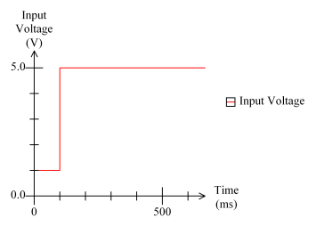
In this application, the user wants to specify the command position through an analog signal. The user wants the RMC to take care of both ramping the target position smoothly from one command position to the next and controlling to the target position.
Suppose the input voltage is as follows:

This would result in an Actual Position with the same shape, although scaled to the user's units. Without a reference filter enabled, the Target Position will match this Actual Position curve:
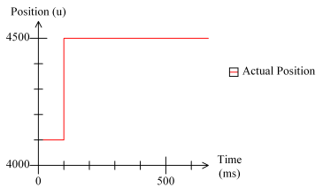
So, without the reference filter, the RMC would not ramp the reference input at all, and jumps in the input current or voltage would be translated directly to jumps in the reference position and jumps in any axes geared to this reference.
To enable reference filtering, the Filter Time Constant parameter must be set to a non-zero value. The Target Position will now appear as follows, as compared to the Actual Position:
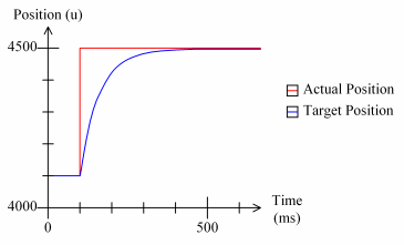
This is a great improvement in that the Target Position no longer has a large step jump. However, two problems remain. First, the Target Velocity at the time of the step jump depends on the amount the Actual Position changed at the step jump. Second, there is a sharp change in the Target Velocity at the time the step jump occurs.
The first problem can be addressed by introducing the Velocity Limit filter parameter. This parameter will limit the Target Velocity in our example as shown:
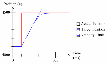
This limits the velocity to a user-specified maximum, but it still leaves us with a sharp change in the Target Velocity at the time of the step jump. The Acceleration Limit can be used to address this issue:
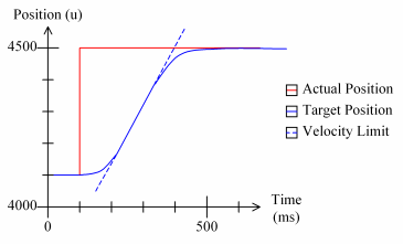
In the above graph, the Target Position is smoothed out at the time of the step jump. This curve should be usable as a reference for RMC100 geared moves. In addition, the Reference Deadband parameter can be used to remove slight ripple in the Target Position while the input voltage is at rest.
Example 2: Quadrature Reference with Quantization Error
Quadrature references will not see large step jumps in the input as is possible for analog inputs. However, the quantization error in applications with low rates of quadrature counts per second can lead to spikes in the reference speed.
Note: This example demonstrates how the reference filter can be used to reduce the effect of quantization error. However, increasing the resolution of the quadrature encoder (for example, from a 1000-line to a 4000-line encoder) can dramatically reduce quantization error as well.
The Actual Position curve shown below demonstrates the effect of quantization error when moving at slow speeds:
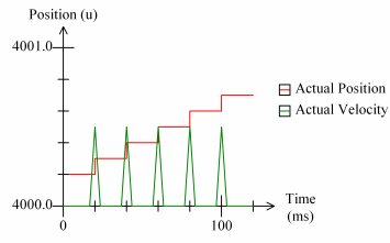
While the effect of quantization on the positions themselves does not appear very great--after all, the position is accurate to one-half a quadrature count--its effect on velocities is much more dramatic.
By applying a Filter Time Constant, the Target Position and Velocity are improved as shown:
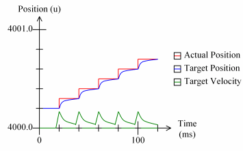
The Velocity and Acceleration Limits are necessary only if the quadrature reference axis moves too quickly at times.
The Reference Deadband can be used to hold the Target Position steady when the reference axis is at rest.
Example 3: Analog Joystick Reference
In this final example, the user wants to use a 0 to 10V input voltage as a position reference for other axes. Unlike the first analog input example, the input voltage in this application will not typically have a step jump.
A typical Actual Position based on the input voltage might look like this:
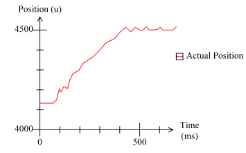
Gearing to a manually-guided voltage such as a joystick often results in rough motion due to mechanical jitter and friction in the potentiometer itself. Therefore, the jaggedness of the previous graph can be reduced by applying the Filter Time Constant.
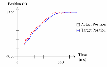
This may be all that is necessary in this application. However, if it is possible for the user to move the joystick too quickly, then the Velocity and Acceleration Limits can be used as in the first example to prevent over-speed conditions. The Reference Deadband can be used to hold the Target Position steady when the reference input is at rest.
Copyright (c) 1997-2015 by Delta Computer Systems, Inc.