This is Part 5 of the complete step-by-step example of setting up and tuning a position/pressure axis.
Part 5: Tuning the position-to-pressure transition.
Now that the position has been tuned and the pressure has been tuned, we can focus on the transition from position to pressure.
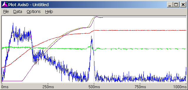
Run Event Step 1 again. It looks like this:

The pressure lags after pressure control begins.
Add Feed Forward to keep pressure from lagging. In this case, the Feed Forwards were set to 13:
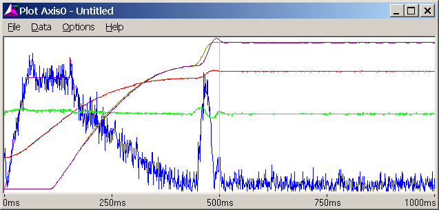
Notice that there is some overshoot when the pressure ramps up and down. This is because the rate of change in pressure is high. During normal operation, the rate should be lower. The system is tuned for a high rate because a system stable at a high rate will generally be stable at a lower rate. The converse is not true, i.e. a system tuned for a low rate will not necessarily be stable at a higher rate.
If the rate of change in pressure is changed (i.e. the ramp time or commanded pressure is changed) the feed forwards may also need to be changed.
The tuning of the transition in this case was unusually simple because "Calculate ramp time" was selected in the Mode word of Event Step 4 (step 4 sets up the pressure before the transition). The RMC automatically calculates a ramp time that will work well. However, some applications require a specific ramp time.
To try the "Set ramp time" option, double-click the Mode word of Event Step 4 and in the Ramp Time field click Use ramp time value. Click OK. Set the ramp time to 200 (in the Speed field). Step 4 now looks like this:

Download the Step table to the RMC by clicking the  button in the Event Steps window. Run Event Step 1. The plot looks like this:
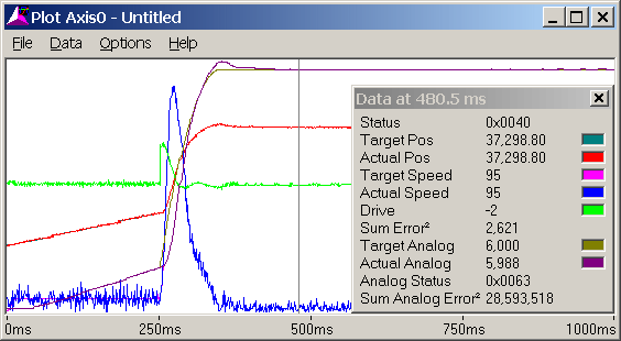
Note how the target pressure begins rising immediately once the pressure reaches Pressure Set A, causing the actual pressure to lag. Because of the short ramp time, the pressure overshoots when it reaches the commanded pressure.
To keep the pressure from lagging when entering pressure control in this case, the speed entering pressure control can changed to closer match the axis speed once pressure control has been entered. This will result in a smaller change in speed at the transition, and less pressure lag.
Currently, the entering speed is 1000 (1 in/sec, from Step 6, Speed field). If we change this to 10000 and run Event Step 1, the plot looks like this:
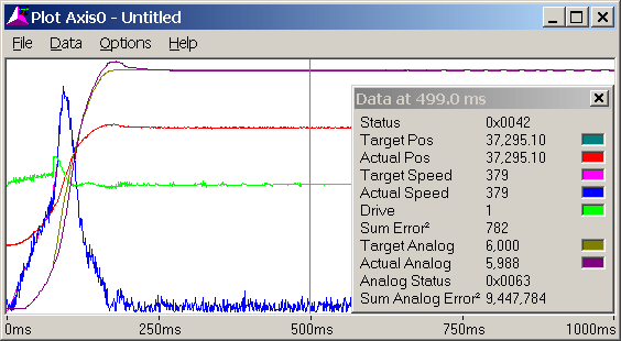
The speed discontinuity upon the transition is much smaller. The speed can be further changed if desired.
The pressure still overshoots. The simplest solution for this is to use a longer ramp time. It may be possible to further tune the system, but it is likely that the system response simply can't handle such fast pressure changes.
Lengthening the ramp time to 1000 msec (Step 4, Speed field), changing the Speed in Step 5 back to 1000 and running Event Step 1 results in the following plot:
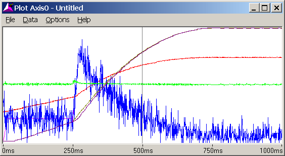
The overshoot disappeared because the pressure did not change as quickly. There is some lag upon the transition, but can likely be corrected by adjusting the entering speed.
Another method of eliminating the lag immediately after the transition is to use the following two parameters:
Integrator Preload
Drive Transfer Percent
Both of these parameters add drive to the Integral Drive when pressure control begins. The difference between these two is that Integrator Preload adds a set value to the drive, while Drive Transfer Percent adds a percentage of the drive immediately prior to the transition.
The Drive Transfer Percent is useful when the entering conditions vary, such as the speed. The Integral Preload is useful when the entering conditions are the same every time.
Warning! These parameters add drive to the Integral Drive. In order for this drive to "unwind" (go towards zero), the Integral Gain must be greater than zero! If the Integral Drive cannot unwind, the system will not control properly.
Setting the Integral Preload to 200 (200 mV of drive), issuing a P cmd, and then running Event Step 1 results in the following plot:
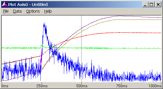
Note that the pressure lags much less immediately after the transition, but the pressure begins to lead because the Integral Drive has not yet unwound. This is probably because "Integrator Active Only at Pressure" was selected in the mode word of Step 4. This causes the integrator to be inactive until the pressure reaches the commanded pressure. The integrator cannot unwind until it reaches commanded pressure.
Selecting "Always Active" in the Integrator Mode field of the Mode word in Step 4 (do this by double-clicking the Mode word in Step 4) and running event Step 1 results in the following plot:
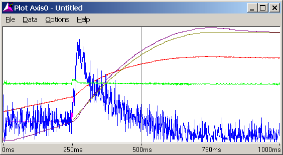
Selecting "Always Active" did help a little, but not much. We will try changing the Integral Gain from 15 to 60 to see if it helps. Doing this and then running Event Step 1 results in the following plot:
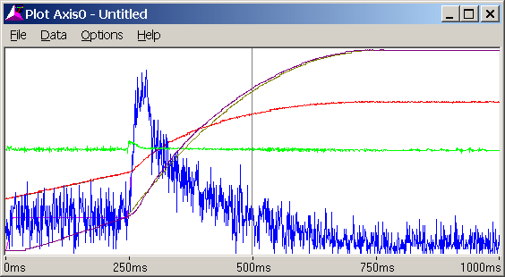
The results are much better. Notice how the pressure leads a little, but it eventually tapers off and the pressure is right on when it reaches the commanded pressure.
Increasing the Integral gain makes a system more prone to oscillation. It may be necessary to reduce it a little.
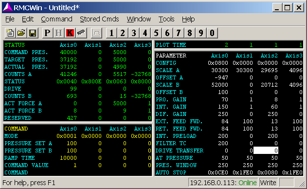
The system is now fairly well tuned. The RMCWin window now looks like this:
Now that the system is tuned, it is important to enable any Auto Stops that were set to Status Only. Double-click the Axis 0 Auto Stop field. The following window appears:
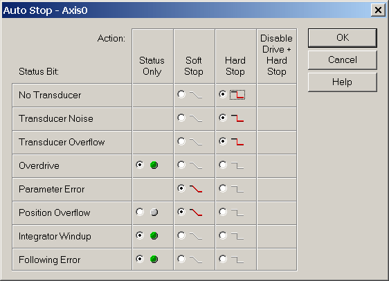
On most systems, it is preferable to have any axis errors cause a Soft or Hard Stop for safety. Additionally, Soft Stops are often desirable because they slowly stop the axis. A Hard Stop immediately puts the drive output to 0 volts, which in some cases can cause a sudden (and potentially dangerous) jerk in the system. Carefully consider your system requirements before determining how to set the Auto Stop bits. In this case, all the Auto Stops are set to Soft Stop. Clicking OK exits the window and issuing a P command initializes the axis with these parameters.
The In Position, At Pressure and Following Error parameters should also be set properly.
The In Position parameter specifies the size of the window in which the axis is considered to be in position. Once the axis is in this window, the In Position bit is turned on. This is useful for determining whether the axis has reached the commanded position. In this example, the axis is considered to be in position when it is within 0.050 inches, so the In Position parameter is set to 50.
The At Pressure parameter is similar to the In Position parameter, but is for the differential pressure axis. In this example, it is set to 50, which is 50 lbs.
The Following Error parameter determines how large the difference between the Target Position and Actual Position can get before the Following Error bit is set in the Status word. Normally, this parameter is set to greater than the worst-case following error to avoid unnecessarily causing an error. In this example, the Following Error parameter is set to 250 (0.25 in.).
The system is now ready to be used for more complicated commands, such as speed control, gearing, splines, synchronized moves, etc.
Copyright (c) 1997-2015 by Delta Computer Systems, Inc.