For general information on the MSTR Block, see Using the MSTR Modicon Ladder Logic Block.
Writing with Modbus Plus is described in Reading and Writing Modbus Plus Registers. Writing with Modbus/TCP is described in Using the Modicon Quantum with the RMC Ethernet Module.
Control Block
In a write operation, the nine control-block registers are assigned as shown:
|
Register |
Content |
|
1st |
Operation: 1 |
|
2nd |
Error Status: This register is filled by the operation. See MSTR Block Error Codes for a complete list. |
|
3rd |
Length: Indicates the number of registers to write. |
|
4th |
Operation-dependent Value: Indicates the address in the slave to write to. Note: When entering register addresses into an MSTR block, do not add 40000 or 400000 to indicate holding registers. MSTR blocks expect the addresses to start at 1, rather than 40001 or 400001.
|
|
5th-9th |
Routing 1-5: The uses of these fields depend on whether Modbus Plus or Modbus/TCP is being used: Modbus Plus: For local addresses, Routing 1 gives the node address, and Routing 2 gives the data path (1-8) to use in the node. Routing 3 through 5 are zeros. For more complicated routing methods, refer to the section on routing path structure in Modbus Plus Network Planning and Installation Guide. Modbus/TCP: Routing 1 is broken into two bytes: the MSB holds the Quantum backplane Slot ID of the NOE module, and the LSB holds the Map Index, which should be zero for the RMC. Routing 2 through 5 holds the four dot-separated values of the RMC IP address (e.g. 192.168.0.5). |
Example (Modbus Plus):
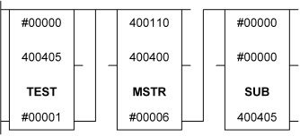
Suppose that you wish to write the six command registers to the first axis of the RMC located at node address 3 whenever the command is non-zero. The command registers to write are located in holding registers 400400 through 400005. You must first choose a location for the 9-register control block. In this example, 400110 to 400118 will be the location. The following network would be used:

This network waits until the command word at 400405 is non-zero and then triggers the MSTR block using the control block below. When the MSTR write operation completes, the command word in 400405 is cleared. Notice that the MSTR enable input is powered for the duration of the operation.
|
Register |
Content |
|
400110 |
1 (decimal): Operation type: Write data |
|
400111 |
0000 (hex): Error status: will be filled in by function |
|
400112 |
6 (decimal): Length: there are 6 command registers on each axis |
|
400113 |
81 (decimal): Address in slave (RMC) memory: This is the address of the first command register on the first axis |
|
400114 |
3 (decimal): Routing 1 (Node address) |
|
400115 |
2 (decimal): Routing 2 (Data path): This could have been 1-8 |
|
400116 |
0 (decimal): Routing 3 |
|
400117 |
0 (decimal): Routing 4 |
|
400118 |
0 (decimal): Routing 5 |
Example (Modbus/TCP):
Suppose that you wish to write the six command registers to the first axes of the RMC located at IP address 192.168.0.5 through a Modicon Ethernet TCP/IP module (140 NOE 211 00) in the Quantum backplane slot #3. You wish to write the command registers whenever the command is non-zero. The command registers to write are located in holding registers 400400 through 400005. You must first choose a location for the 9-register control block. In this example, 400110 to 400118 will be the location. The following network would be used:

This network waits until the command word at 400405 is non-zero and then triggers the MSTR block using the control block below. When the MSTR write operation completes, the command word in 400405 is cleared. Notice that the MSTR enable input is powered for the duration of the operation.
|
Register |
Content |
|
400110 |
1 (decimal): Operation type: Write data |
|
400111 |
0000 (hex): Error status: will be filled in by function |
|
400112 |
6 (decimal): Length: there are 6 command registers on each axis |
|
400113 |
81 (decimal): Address in slave (RMC) memory: This is the address of the first command register on the first axis |
|
400114 |
0300 (hex): The high byte holds the Quantum backplane slot ID (3). The low byte holds the Map Index, which should be set to zero when communicating with the RMC. |
|
400115 |
192 (decimal): Routing 2: First byte of the IP address: 192.168.0.5 |
|
400116 |
168 (decimal): Routing 3: Second byte of the IP address: 192.168.0.5 |
|
400117 |
0 (decimal): Routing 4: Third byte of the IP address: 192.168.0.5 |
|
400118 |
5 (decimal): Routing 5: Fourth byte of the IP address: 192.168.0.5 |
Copyright (c) 1997-2015 by Delta Computer Systems, Inc.