For general information on the MSTR Block, see Using the MSTR Modicon Ladder Logic Block.
Note: This operation is only available for Modbus Plus and not Modbus/TCP.
This operation reads a portion of a 12-register Peer Cop Health table. For a description of Peer Cop, see Using Modicon’s Peer Cop to Read Global Data. This table consists of a collection of one bit per node address for each of three types of Peer Cop transfer. For the RMC, only the Global Input portion is useful since Specific Inputs and Outputs are not used. Each bit that is set indicates that the device with that address is connected using Peer Cop:
|
Status Type |
Word Index |
MSB |
Node Addresses |
LSB |
|||||||||||||
|
Global Input |
0 |
16 |
15 |
14 |
13 |
12 |
11 |
10 |
9 |
8 |
7 |
6 |
5 |
4 |
3 |
2 |
1 |
|
|
1 |
32 |
31 |
30 |
29 |
28 |
27 |
26 |
25 |
24 |
23 |
22 |
21 |
20 |
19 |
18 |
17 |
|
|
2 |
48 |
47 |
46 |
45 |
44 |
43 |
42 |
41 |
40 |
39 |
38 |
37 |
36 |
35 |
34 |
33 |
|
|
3 |
64 |
63 |
62 |
61 |
60 |
59 |
58 |
57 |
56 |
55 |
54 |
53 |
52 |
51 |
50 |
49 |
|
Specific Output |
4 |
16 |
15 |
14 |
13 |
12 |
11 |
10 |
9 |
8 |
7 |
6 |
5 |
4 |
3 |
2 |
1 |
|
|
5 |
32 |
31 |
30 |
29 |
28 |
27 |
26 |
25 |
24 |
23 |
22 |
21 |
20 |
19 |
18 |
17 |
|
|
6 |
48 |
47 |
46 |
45 |
44 |
43 |
42 |
41 |
40 |
39 |
38 |
37 |
36 |
35 |
34 |
33 |
|
|
7 |
64 |
63 |
62 |
61 |
60 |
59 |
58 |
57 |
56 |
55 |
54 |
53 |
52 |
51 |
50 |
49 |
|
Specific Input |
8 |
16 |
15 |
14 |
13 |
12 |
11 |
10 |
9 |
8 |
7 |
6 |
5 |
4 |
3 |
2 |
1 |
|
|
9 |
32 |
31 |
30 |
29 |
28 |
27 |
26 |
25 |
24 |
23 |
22 |
21 |
20 |
19 |
18 |
17 |
|
|
10 |
48 |
47 |
46 |
45 |
44 |
43 |
42 |
41 |
40 |
39 |
38 |
37 |
36 |
35 |
34 |
33 |
|
|
11 |
64 |
63 |
62 |
61 |
60 |
59 |
58 |
57 |
56 |
55 |
54 |
53 |
52 |
51 |
50 |
49 |
Control Block
The nine control-block registers are assigned in a Peer Cop Health operation as shown:
|
Register |
Content |
|
1st |
Operation: 9 |
|
2nd |
Error Status: This register is filled by the operation. See MSTR Block Error Codes for a complete list. |
|
3rd |
Length: Indicates the number of words to transfer. |
|
4th |
Word Index: Gives the index of the first Peer Health word to read. |
|
5th-9th |
Routing 1-5: Unused. Set zeros. |
Example
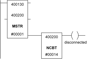
Suppose that we have an RMC device on a Modbus Plus network with a node address of 3. We want to set a coil called ”r;disconnected” when the RMC is not found on the network. We will read one of the four Peer Cop Global Input Health registers into register 400200. We must first choose a location for the 9-register control block. In this example, 400130 to 400138 is the location. The following network would be used:

The MSTR block indicates it will do an operation using the control block beginning at 400130, using the one register at 400200. When this block is finished, we look at the third least significant bit, which represents node 3. If this bit is cleared, then the RMC is disconnected.
The next step is to set up the control block:
|
Register |
Content |
|
400130 |
9 (decimal): Operation type: Peer Cop Health |
|
400131 |
0000 (hex): Error status: filled in by function |
|
400132 |
1 (decimal): Length: we only want one register |
|
400133 |
0 (decimal): Word Index: we want the first word in the table |
|
400134-8 |
0 (decimal): Unused |
Copyright (c) 1997-2015 by Delta Computer Systems, Inc.