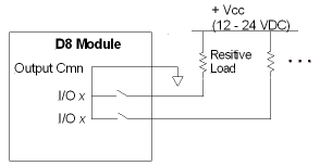
Figure 2: SSR switching resistive load: low-side configuration.
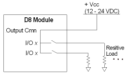
Figure 3: SSR switching resistive load: high-side configuration.
Each discrete I/O point on the D8 expansion module is individually configurable in software as an input or output. Since there is just one input common and one output common, all inputs must be the same polarity, and all outputs must be the same polarity, but inputs need not be the same polarity as outputs, that is, outputs can switch high side or low side, and inputs can be active high or low.
Inputs and outputs are 24Vdc rated, and optically isolated from controller. Since all inputs share a common connection, there is no isolation between input points. By the same token, all outputs share a common pin and therefore do not have isolation between outputs.
Wire clamp screws must be tightened to max 7 b-in (0.8Nm).
Pin-Out
|
Pin |
Function |
|
Output Cmn |
Common to one side of all outputs |
|
I/O 0 |
Input or Output |
|
I/O 1 |
Input or Output |
|
I/O 2 |
Input or Output |
|
I/O 3 |
Input or Output |
|
I/O 4 |
Input or Output |
|
I/O 5 |
Input or Output |
|
I/O 6 |
Input or Output |
|
I/O 7 |
Input or Output |
|
Input Cmn |
Common to one side of all inputs |
Discrete Outputs
Each discrete output is a solid state relay (SSR). When it is "OFF", it has high impedance, and when "ON" it has low impedance (50 Ω maximum, 25 Ω typical). Because the output is isolated, the user must power it externally. The maximum current and voltage for the output is 75 mA (50 mA for Class I, Div 2) and 30 V.
Using Outputs with Resistive Loads
|
|
|
|
Figure 2: SSR switching resistive load: low-side configuration. |
Figure 3: SSR switching resistive load: high-side configuration. |
![]() Example: Calculating maximum current
for resitive load.
Example: Calculating maximum current
for resitive load.
Using Outputs with Inductive Loads
External fuses should be used to protect the SSRs if there is a possibility of over-current. When switching inductive loads, it is important to place a diode or tranzorb across the load to protect the switch when transitioning from an ”ON” to an ”OFF” state. Otherwise, the collapsing magnetic field can cause a reverse voltage spike in excess of the 30 V rating of the SSR. See figures below for details.
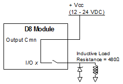
Figure 1: SSR switching inductive inductive load: high-side configuration.
![]() Example: Calculating maximum current
for inductive load.
Example: Calculating maximum current
for inductive load.
Discrete Inputs
The discrete inputs are compatible with signal levels ranging from 12V to 24V. Each input draws a maximum of 2.6mA with a 12V or 24V input. Most PLC outputs can be connected to the DI/O inputs directly. The exception is open collector (sinking) outputs. See the discussion below for using sinking outputs.
Wiring Diagrams
The following are some input wiring diagrams:
|
|
|
|
Figure 4: Direct connection to Programmable Controller. |
Figure 5: Relay Connection from Programmable Controller. |
Using D8 Inputs with Open Collector Outputs
The D8's discrete inputs can be used with open collector (sinking) outputs. There are three configurations that can be used to drive the D8 inputs from an open-collector output:
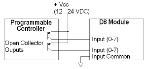
Figure 6: PNP Configuration: This configuration is the most popular for open collector PNP outputs.
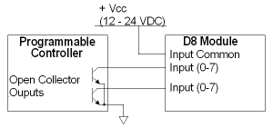
Figure 7: Open Collector Outputs to D8 Inputs with Input Common Connected to Vcc.
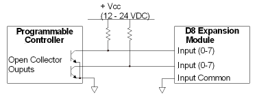
Figure 8: Open Collector Outputs to D8 Inputs with Input Common Connected to ground.
For 24VDC power, the pull-up resistor should be a 4.7kΩ, ¼ watt resister. The output must be capable of switching 2.6mA when closed. When the open collector output is open, the DI/O input sees 11.8V @ 2.6mA.
For 12VDC power, the pull-up resistor should be a 1 kΩ, ¼ watt resister. The output must be capable of switching 2.6mA when closed. When the open collector output is open, the DI/O input sees 9.4V @ 2.6mA.
See Also
Copyright © 2025 Delta Computer Systems, Inc. dba Delta Motion