The AP2 expansion module can be wired to voltage or current feedback transducers.
Use shielded twisted pairs for all connections to inputs and outputs. Route the transducer wiring separate from other wiring. You must provide the power supplies needed by your transducers. See Wiring Guidelines for general wiring information.
Wire clamp screws must be tightened to max 7 lb-in (0.8Nm).
All commons are internally connected.
NOTE:
The example schematics do not include transducer pin numbers, color codes,
or power supply requirements, since these vary between different transducers.
To determine your power supply needs and connector pin-outs or cable
color codes, consult your transducer manufacturers documentation.
NOTE:
If the input is disconnected, input voltage will be pulled down ≤ -10V.
Wiring Diagrams and Instructions
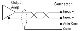
Voltage Feedback Transducers
Voltage feedback transducers can be connected directly to the Input + and Input - connections of the desired axis. The Anlg Cmn and Case pins may be shared by the axes. The following configuration is recommended:
Current Feedback Transducers
Current feedback transducers are connected in the same way as voltage transducers except that a jumper must be inserted between the Input+ and Jumper for 4-20 mA pins. The label indicates where this jumper should be connected. This places a resistor internal to the RMC across the two inputs, thus converting the current to a voltage input. The following wiring diagram shows a suggested configuration:
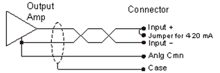
2-Wire Current Transducer
See Also
Copyright © 2026 Delta Computer Systems, Inc. dba Delta Motion