This topic covers the wiring of the RMC200 U14 Module. See Wiring Guidelines for general wiring information.
Pin-Out
Terminal Block 1 (top)
|
Description |
|
Pin |
|
Description |
|
|
Analog Input Common |
AInCmn |
1 |
2 |
AIn0+ |
Analog Input 0+ |
|
Shield Connection |
Case |
3 |
4 |
AIn0- |
Analog Input 0- |
|
Analog Input 1 |
AInCmn |
5 |
6 |
AIn1+ |
Analog Input 1 |
|
Case |
7 |
8 |
AIn1- |
||
|
Analog Input 2 |
AInCmn |
9 |
10 |
AIn2+ |
Analog Input 2 |
|
Case |
11 |
12 |
AIn2- |
||
|
Analog Input 3 |
AInCmn |
13 |
14 |
AIn3+ |
Analog Input 3 |
|
Case |
15 |
16 |
AIn3- |
||
|
Analog Output Common |
AOutCmn |
17 |
18 |
AOut0 |
Analog Output 0 |
|
Shield connection |
Case |
19 |
20 |
AOutCmn |
Analog Output Common |
|
Analog Output 1 |
AOutCmn |
21 |
22 |
AOut1 |
Analog Output 1 |
|
Case |
23 |
24 |
AOutCmn |
||
The AInCmn pins are internally connected. The AOutCmn pins are internally connected.
Terminal Block 2 (bottom)
|
Description |
|
Pin |
|
Description |
|
|
Registration/Quad Z 0+ |
Reg/Z0+ |
1 |
2 |
Clk/A0+ |
SSI Clk/MDT Int/Quad A 0+ |
|
Registration/Quad Z 0- |
Reg/Z0- |
3 |
4 |
Clk/A0- |
SSI Clk/MDT Int/Quad A 0- |
|
SSI/MDT/Quad Common |
S/QCmn |
5 |
6 |
Dat/B0+ |
SSI Data/MDT Ret/Quad B 0+ |
|
Shield Connection |
Case |
7 |
8 |
Dat/B0- |
SSI Data/MDT Ret/Quad B 0- |
|
Registration/Quad Z 1+ |
Reg/Z1+ |
9 |
10 |
Clk/A1+ |
High-speed Channel 1 |
|
Registration/Quad Z 1- |
Reg/Z1- |
11 |
12 |
Clk/A1- |
|
|
SSI/MDT/Quad Common |
S/QCmn |
13 |
14 |
Dat/B1+ |
|
|
Shield Connection |
Case |
15 |
16 |
Dat/B1- |
|
|
Discrete I/O 0+ |
D0+ |
17 |
18 |
D1+ |
Discrete I/O 1 |
|
Discrete I/O 0- |
D0- |
19 |
20 |
D1- |
|
|
Discrete I/O 2 |
D2+ |
21 |
22 |
D3+ |
Discrete I/O 3 |
|
D2- |
23 |
24 |
D3- |
||
The S/QCmn pins are internally connected.
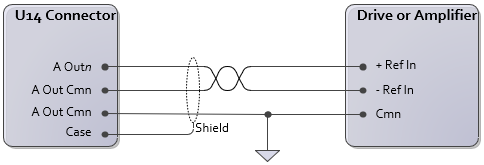
U14 Analog Outputs
The U14 analog outputs provide ±10 V, 4-20 mA, or ±20 mA.
Wiring the U14 Analog Output to Differential Inputs
Differential inputs provide the best noise immunity. This is indicated by individual +, -, and cmn inputs on the drive or amplifier. The U14 provides two Analog Output Common pins per analog output to make analog differential wiring easy.
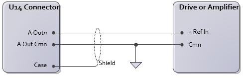
Wiring the U14 Analog Output to Single-ended Inputs
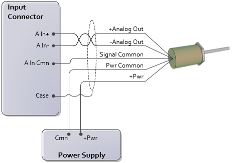
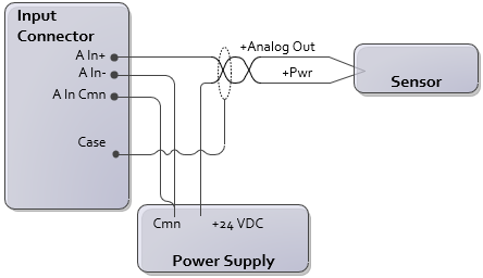
U14 Analog Inputs
Voltage Transducers
To reduce electrical interference:
In- and Cmn must be connected, either internal to the transducer or externally as close as possible to the transducer.
Use individually shielded twisted-pair wire.
Connect cable shield to earth ground on one end only.
If transducer has only one common, connect Pwr Supply Common and RMC Cmn to it. For best results, make this connection at the transducer.
4- or 5-wire Voltage
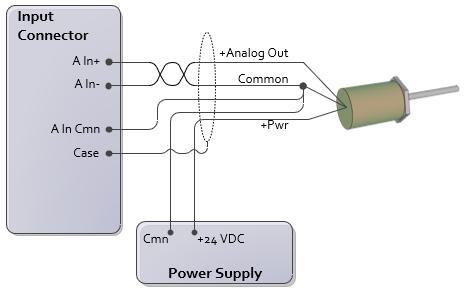
3-wire Voltage
Current Transducers
To reduce electrical interference:
Use individually shielded twisted-pair wire.
Connect cable shield to ground on one end only.
2-wire Current
4-wire Current
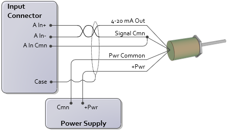
The connection of In- to Cmn should be made as close as possible to the transducer.
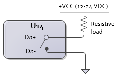
U14 Discrete Outputs D0-D3
The DI/O point must first be configured in RMCTools to be an output. The U14 discrete outputs are solid state relays. The off state is high impedance, the on state is low impedance (8Ω max, 5Ω typical). Max current 75 mA. Max voltage 30 V. Each DI/O point is individually isolated.
Outputs can be wired in either a high-side or low-side configuration.

|
|
The load resistance must be sized such that the maximum current through the SSR does not exceed 75 mA. The maximum current is calculated with the following equation:
Current = Vcc / RLoad
For example, if the supply voltage Vcc is 24V, and the load resistance is 480Ω, the current will be:
Current = 24V / 480Ω = 50mA
which is under the 75 mA limit.
Using Outputs with Inductive Loads
External fuses should be used to protect the SSRs if there is a possibility of over-current. When switching inductive loads, it is important to place a diode or tranzorb across the load to protect the switch when transitioning from an ”ON” to an ”OFF” state. Otherwise, the collapsing magnetic field can cause a reverse voltage spike in excess of the 30 V rating of the SSR.
SSR switching inductive inductive load with high-side configuration:
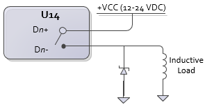
When calculating the current through the SSR, use the same type of calculation as above, with the coil resistance as the load.
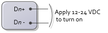
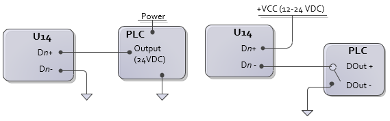
U14 Discrete Inputs D0-D3
The DI/O point must first be configured in RMCTools to be an input. Each input is individually isolated and has Dn+ and Dn- connections. To turn on a discrete input, apply a 12-24 Vdc voltage. Max current draw is 7 mA.
Examples:
U14 Reg/Z Inputs
When using the Reg/Z Inputs as an Index (Z) input from the encoder together with the A and B quadrature signals, refer to the U14 Quadrature Channel section below instead.
The Reg/Z inputs are individually isolated. When the high-speed channel associated with the Reg/Z input is in quadrature mode and is assigned to an axis, the Reg/Z input can be configured as single-ended or differential, and supports 5-24V levels. When the high-speed channel associated with the Reg/Z input is not in quadrature mode, or is not assigned to an axis, the Reg/Z input will be set as a single-ended HTL input with a 12V threshold.
Differential
For this wiring configuration, set the Z Input Type axis parameter as follows:
|
Signal |
|
|
RS-422 Push-pull with complements, 5V |
RS-422 |
|
Differential HTL, 12-24V Push-pull with complements, 12-24V |
Differential HTL |
Note: Before connecting HTL signals to the input, set the Z Input Type parameter to HTL.
Note: S/Q Cmn must be connected to the common used by the Reg/Z input signal source.
Note: The Reg/Z input shares the same common (S/Q Cmn) as the A and B inputs.
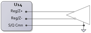
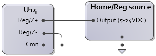
Single-Ended
For this wiring configuration, set the Z Input Type and HTL Threshold axis parameters as follows:
|
Signal |
||
|
TTL |
TTL |
n/a |
|
PNP prox switch |
DI (better noise immunity than HTL) |
n/a |
|
Push-pull without complements, 12V* |
Single-ended HTL |
7V |
|
Push-pull without complements, 24V* |
Single-ended HTL |
12V |
*These signal input types are available, but not recommended when using the Reg/Z as a home or registration input. These are typically only used as a Z signal together with the A and B signal from the encoder.
Note: Before connecting HTL signals to the input, set the Z Input Type parameter to HTL.
Note: For single-ended connection, Reg/Z- must be connected to Cmn.
U14 Quadrature Channel
Differential Quadrature Wiring
Use this wiring diagram for encoders with the following outputs:
RS-422
5V Differential
Differential HTL (High Threshold Logic) for signals from 12V to 24 V
Push-pull with complements
For this wiring configuration, set the AB Input Type and Z Input Type axis parameters as follows:
|
Encoder Signal |
|
|
RS-422 Push-pull with complements, 5V |
RS-422 |
|
Differential HTL, 12-24V Push-pull with complements, 12-24V |
Differential HTL |
Note: Before connecting HTL signals to the input, set the AB Input Type and Z Input Type parameters to HTL!
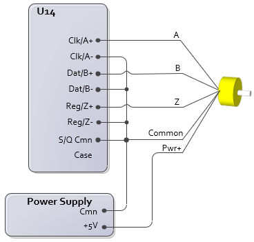
Single-ended Quadrature Wiring (Not Recommended)
Delta does not recommend single-ended quadrature encoders due to poor noise immunity and a low maximum count frequency.
Use this wiring diagram for encoders with the following outputs:
TTL*
Push-pull without complements, 5-24V
*If these signals have complements, the complements are not used in this wiring configuration.
For this wiring configuration, set the AB Input Type, Z Input Type, and HTL Threshold axis parameters as follows:
|
Encoder Signal |
||
|
TTL* |
TTL |
n/a |
|
Push-pull without complements, 12V |
Single-ended HTL |
7V |
|
Push-pull without complements, 24V |
Single-ended HTL |
12V |
*Some encoders may not have adequate drive capability to support termination on the input. If termination is desired, termination can be enabled in software and Clk/A-, Dat/B-, or Reg/Z- need to be connected to S/Q Cmn.
Termination
Termination is software selectable via an axis parameter. Input termination should always be applied when connecting a point-to-point RS-422 encoder signal. For daisy-chained quadrature feedback (connecting one encoder to multiple inputs), only the last input in the chain should have termination. The termination parameter is available only if the input is RS-422 or TTL.
After configuring the U14 channel as quadrature, and assigning the input to an axis, the AB Termination and Z Termination parameters will be available on the All tab in the Axis Parameters Pane, in the Feedback section. Choose Enabled to apply termination.
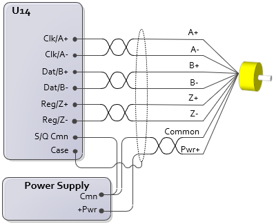
U14 SSI Channel
SSI uses differential line driver (RS422) clock and data signals.
SSI Input
When using the high-speed channel as an SSI input, wire it to the transducer or encoder as follows:
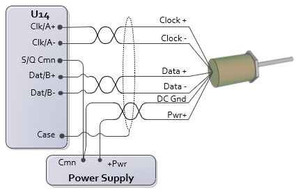
Wiring Instructions
Connect the transducer DC ground to the U14 S/Q Cmn. The S/Q Cmn must be connected to the transducer, or the signals will not be read correctly!
The transducer power supply is not provided by the RMC. The user must supply a power supply. The power supply common may be connected to the same common that is connected to the RMC power supply Cmn.
Max Cable Length
|
Clock Rate |
Maximum Cable Length* |
|
100 kHz |
2100 ft (640 m) |
|
150 kHz |
1360 ft (415 m) |
|
230 kHz |
850 ft (255 m) |
|
250 kHz |
770 ft (235 m) |
|
375 kHz |
475 ft (145 m) |
|
500 kHz |
325 ft (99 m) |
|
921 kHz |
120 ft (37 m) |
|
971 kHz |
110 ft (34 m) |
|
1000 kHz |
100 ft (30 m) |
|
1500 kHz |
25 ft (7.5 m) |
|
2500 kHz |
3 ft (1 m) |
* The cable lengths are approximate, and may be affected by the type of wire and transducer.
Termination
SSI signals need to be terminated at the input end. For a typical RMC SSI input that is connected directly to an SSI device (the transducer or encoder), the ±Data signals are an input to the RMC, and need to be terminated. The ±Clock signals are an outputs from the RMC, so ±Clock termination on the RMC side doesn't apply.
Termination is on by default, as indicated by the SSI Termination axis parameter in the associated axis.
SSI Monitor Mode
SSI Monitor Mode normally requires daisy-chaining the SSI wiring. When wiring a daisy-chained SSI system, the SSI master should be on one end of the daisy chain with the SSI device on the other end, and any monitoring modules in the middle of the daisy chain.
Wire the SSI device to the first monitoring RMC as illustrated in the SSI Inputs section above, then daisy chain the first RMC to the other RMCs. Apply termination only to the SSI master.
Termination
SSI signals need to be terminated at the input end. For SSI Monitor, both the ±Data and ±Clock on the RMC are inputs, so any termination applies to both ±Data and ±Clock. If the SSI Monitor is in the middle of a daisy-chained SSI configuration, it should not have termination, and only the last input in the chain should have termination. If the SSI Monitor is the endpoint of the wiring, then termination should be applied.
For U14 channels configured as SSI Monitor, after assigning the input to an axis, the SSI Termination parameter will be available on the All tab in the Axis Parameters Pane, in the Feedback section.
SSI Echo Mode
For SSI Echo Mode, the U14 channel acts like an SSI encoder. A controller sends the ±Clock signal to the U14 channel, and the U14 channel returns the ±Data signal.
Wire the U14 channel 1 as if it is the SSI encoder, with the remote controller being the SSI master. This is simply the opposite of the SSI Input wiring diagram above.
U14 MDT Channel
The U14 module interfaces only to transducers with Differential Line Driver (RS422) signals. The transducer pin names may vary by manufacturer.
|
Pin |
Function |
Possible Manufacturer Designation |
|
Clk/A+ |
MDT Interrogation+ |
Interrogate+ Input |
|
Clk/A- |
MDT Interrogation- |
Interrogate- Input |
|
S/Q Cmn |
MDT Common |
|
|
Dat/B+ |
MDT Return+ |
Pulse+ Output |
|
Dat/B- |
MDT Return- |
Pulse- Output |
|
Case |
Shield Connection |
|
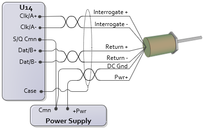
Wiring instructions:
Connect the transducer DC ground to the U14 S/Q Cmn. The S/Q Cmn must be connected to the transducer, or the signals will not be read correctly!
The transducer power supply is not provided by the RMC. The user must supply a power supply. The power supply common may be connected to the same common that is connected to the RMC power supply Cmn.
See Also
Wiring Guidelines | U14 Module
Copyright © 2026 Delta Computer Systems, Inc. dba Delta Motion