The Q4 Module can be wired to quadrature encoder signals. For best noise immunity and speed performance, Delta recommends using RS-422 encoders, with shielded twisted pairs for all connections to inputs and outputs. Route the transducer wiring separate from other wiring. You must provide the power supplies needed by your transducers.
See Wiring Guidelines for general wiring information.
Pin-Out
Terminal Block 1 (top)
|
Description |
|
Pin |
|
Description |
|
|
Input 0 Z+ |
Z0+ |
1 |
2 |
A0+ |
Input 0 A+ |
|
Input 0 Z- |
Z0- |
3 |
4 |
A0- |
Input 0 A- |
|
Input 0 Home |
Hm0 |
5 |
6 |
B0+ |
Input 0 B+ |
|
Encoder and Home Common |
Cmn |
7 |
8 |
B0- |
Input 0 B- |
|
Shield Connection |
Case |
9 |
10 |
Cmn |
Encoder and Home Common |
|
Input 1 Z+ |
Z1+ |
11 |
12 |
A1+ |
Input 1 A+ |
|
Input 1 Z- |
Z1- |
13 |
14 |
A1- |
Input 1 A- |
|
Input 1 Home |
Hm1 |
15 |
16 |
B1+ |
Input 1 B+ |
|
Encoder and Home Common |
Cmn |
17 |
18 |
B1- |
Input 1 B- |
|
Shield Connection |
Case |
19 |
20 |
Cmn |
Encoder and Home Common |
|
Registration 0 Input |
Reg0+ |
21 |
22 |
Reg1+ |
Registration 1 Input |
|
Reg0- |
23 |
24 |
Reg1- |
||
All the Cmn pins in Terminal Blocks 1 and 2 are internally connected.
Terminal Block 2 (bottom)
|
Description |
|
Pin |
|
Description |
|
|
Input 2 Z+ |
Z2+ |
1 |
2 |
A2+ |
Input 2 A+ |
|
Input 2 Z- |
Z2- |
3 |
4 |
A2- |
Input 2 A- |
|
Input 2 Home |
Hm2 |
5 |
6 |
B2+ |
Input 2 B+ |
|
Encoder and Home Common |
Cmn |
7 |
8 |
B2- |
Input 2 B- |
|
Shield Connection |
Case |
9 |
10 |
Cmn |
Encoder and Home Common |
|
Input 3 Z+ |
Z3+ |
11 |
12 |
A3+ |
Input 3 A+ |
|
Input 3 Z- |
Z3- |
13 |
14 |
A3- |
Input 3 A- |
|
Input 3 Home |
Hm3 |
15 |
16 |
B3+ |
Input 3 B+ |
|
Encoder and Home Common |
Cmn |
17 |
18 |
B3- |
Input 3 B- |
|
Shield Connection |
Case |
19 |
20 |
Cmn |
Encoder and Home Common |
|
Registration 2 Input |
Reg2+ |
21 |
22 |
Reg3+ |
Registration 3 Input |
|
Reg2- |
23 |
24 |
Reg3- |
||
All the Cmn pins in Terminal Blocks 1 and 2 are internally connected.
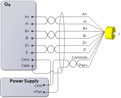
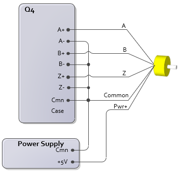
Differential Quadrature Wiring
Use this wiring diagram for encoders with the following outputs:
RS-422
5V Differential
Differential HTL (High Threshold Logic) for signals from 12V to 24 V
Push-pull with complements
Axis Parameters
For this wiring configuration, set the AB Input Type and Z Input Type axis parameters as follows:
|
Encoder Signal |
|
|
RS-422 Push-pull with complements, 5V |
RS-422 |
|
Differential HTL, 12-24V Push-pull with complements, 12-24V |
Differential HTL |
Diagram
Single-ended Quadrature Wiring (Not Recommended)
Delta does not recommend single-ended quadrature encoders due to poor noise immunity and a low maximum count frequency.
Use this wiring diagram for encoders with the following outputs:
TTL*
Push-pull without complements, 5-24V
*If these signals have complements, the complements are not used in this wiring configuration.
Axis Parameters
For this wiring configuration, set the AB Input Type, Z Input Type, and HTL Threshold axis parameters as follows:
|
Encoder Signal |
||
|
TTL* |
TTL |
n/a |
|
Push-pull without complements, 12V |
Single-ended HTL |
7V |
|
Push-pull without complements, 24V |
Single-ended HTL |
12V |
*Some encoders may not have adequate drive capability to support termination on the input. If termination is desired, termination can be enabled in software and A-, B-, or Z- need to be connected to Cmn.
Diagram
For single-ended connection, A-, B- and Z- must be connected to Cmn.
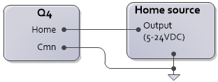
Home Input Wiring
Use this wiring diagram for the home inputs on the Q4 module. The home input supports 5-24V levels.
Axis Parameters
For this wiring configuration, set the H Input Type axis parameter as follows:
|
Home Signal |
|
|
TTL |
TTL |
|
12-24V |
DI |
Diagram
Registration Input Wiring
Use this wiring diagram for the registration inputs on the Q4 module. The registration inputs are individually isolated and support 5-24V levels.
Axis Parameters
For this wiring configuration, set the R Input Type axis parameter as follows:
|
Home Signal |
|
|
TTL |
5V |
|
12-24V |
12-24V |
Diagram

See Also
Copyright © 2026 Delta Computer Systems, Inc. dba Delta Motion